Users Manual & Installation Guide
PV- 1800: Power supply module with GSM MODEM
Page 9 / 21
AT commands
All functions of the modem are carried out by AT commands from a computer application. For
documentation of the AT command set please see “Integrators Manual” for GM47 from Sony
Ericsson, at http://www.eurodis.com/wireless/htm/suppliers_sonyericsson.asp
Modem on/off
The PV-18xx has circuitry that automatically turns the modem on after a system reset, by activating
its ON/OFF input. From software, you can later activate the ON/OFF input, please see section PV-
1800 register interface.
RS232 port (CN6)
The PV-1800 and PV-1700 is equipped with a 16C550 compatible RS232 port which can be
accessed through a 10pin boxheader (CN6).
Setting up RS232
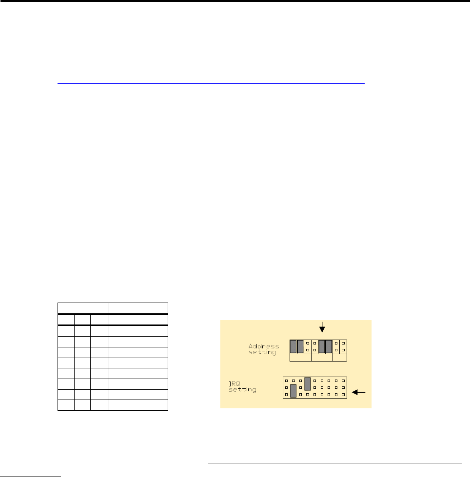
The setup of the serial port is configured by two jumper blocks.
The address is set by placing one or more jumpers in the positions 4 to 6 in section COM_B.
The table shows how different COM ports can be configured:
ST1 Base address
4 5 6 COM_B
0 0 0 Disabled
0 0 1 2C8
0 1 0 2D8
0 1 1 2E8 (COM4)
1 0 0 2F8 (COM2)
1 0 1 3D8
1 1 0 3E8 (COM3)
1 1 1 3F8 (COM1)
This table is also printed on the board.
The IRQ used for the RS232 is set in section IRQ_B. Place one jumper in this section to select an
IRQ number in the interval IRQ3 to IRQ15. Be aware not to make conflict with COM-ports on the
CPU module.
RS232 connector (CN6)
The serial connector is a 10pin 2.54mm boxheader placed on the edge of the module.
This pinout is chosen so that a 10-wire ribbon cable with a 10-pin connector in one end and a DB9
male connector in the other end can be used. In this way, the DB9 male connector acts like a serial
port in a PC.
+
,-
,-#
.
%- %-#'$


