


Users Manual & Installation Guide
PV-
SERIES
4-P
ORT
RS232/RS422/RS485
Page 4 of 7
I
NSTALLATION
G
UIDE
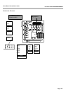
Please refer to the schematic outline on page 5.
P
RECAUTIONS TO
ESD
Please note, that the Micronix PV modules must be handled with respect to ESD (Electrostatic Discharge).
Electrostatic Discharge to the PV modules must be avoided.
Before removing the module from the protection bag, the user must be discharged using a grounded wrist
ribbon.
S
ETTING THE
I/O
A
DDRESS
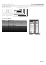
The I/O address for channel A through D is set by the corresponding rotary-switch.
The individual positions are printed on the PCB.
E
XAMPLE
Setting channel A to I/O address 2F8, turn rotary-switch labelled "A" to position "7".
S
ETTING THE
I
NTERRUPT
N
UMBER
(I
NDIVIDUALLY
)
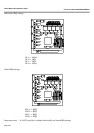
The IRQ number for channel A through D, is set by the corresponding pin column array.
The individual positions are printed on the PCB.
E
XAMPLE
See IRQ select page 6.
S
ETTING THE
I
NTERRUPT
N
UMBER
(S
HARED
)
If shared interrupt is used, the IRQ number for all four channels will be the same.
E
XAMPLE
See shared IRQ settings page 7.
S
ETTING THE
B
AUD RATE
The baud rate is set by the software application. Each port is compatible to a normal PC COM-port and should
be accessed accordingly. Operating systems and standard software applications have utilities for that.
For more sophisticated programming and specific control of handshake signals, please refer to a 16C550
manual. This manual can be ordered from a National Semiconductor representative.
H
IGH
S
PEED
-
VERSIONS
:
B
AUD RATE
N
OTICE
The actual baud rate will be 4 times the baud rate set by the software.
5V
ONLY VERSIONS
(5
V
):
These versions do not require +/-12V from the PC/104 bus.