


CABLE SPECIFICATIONS
The physical characteristics of the media cable must meet or exceed IEEE 802.3
specifications.
Fiber Cable
MULTIMODE
Fiber Optic Cable Recommended: 62.5 / 125 µm multimode fiber
Optional: 100 / 140 µm multimode fiber
85 / 125 µm multimode fiber
50 / 125 µm multimode fiber
Fiber Optic Transmitter Power: min: -19.0 dBm max: -14.0 dBm
Fiber Optic Receiver Sensitivity: min: -32.5 dBm max: -14.0 dBm
Wavelength : 850nM
Bit error rate: ≤10-9
Maximum Cable Distance: 2 kilometers
SINGLEMODE
Fiber Optic Cable Recommended: 9 µm singlemode fiber
Wavelength: 1300nM
Bit error rate: ≤10-9
Fiber-optic Transmitter Power: min: -15.0 dBm max: -8.0 dBm
Fiber-optic Receiver Sensitivity: min: -32.5 dBm max: -8.0 dBm
Maximum Cable Distance: 20 kilometers
Copper Cable
Category 5 twisted-pair copper wire is required. Either shielded twisted-
pair (STP) or unshielded twisted-pair (UTP) can be used. DO NOT USE
FLAT OR SILVER SATIN WIRE.
CATEGORY 5:
Gauge 24 to 22 AWG
Attenuation 20 dB/1000’ @ 10 MHz
Differential Characteristic Impedance 100 Ω ±10% @ 10 MHz
Maximum Cable Distance: 100 meters
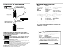
INSTALLATION
Set Switches
Use small flatblade screwdriver or similar device to set recessed switches
according to site installation.
• Set EACH MDI/MDI-X switch to MDI for cable connection between switch
and media converter OR to MDI-X for cable connection between media
converter and terminal, transceiver or network interface card (NIC).
• Referring to drawing on page 2, set four-position switch according to
network configuration.
NOTE: If connecting two (2) media converters in series, set the PST (#4)
switch on one media converter to the UP position AND set the PST (#4)
switch on the other media converter to the DOWN position.
Install Slide-In-Module in E-MCC-1600 Chassis
• Remove Media Converter Slide-in-Module protective plate from
selected installation slot by removing two (2) screw that secures plate to
front of E-MCC-1600.
• Carefully slide Media Converter Slide-in-Module into installation slot,
aligning Media Converter Slide-in-Module with installation guides.
NOTE: Ensure that the Media Converter Slide-in-Module is firmly seated
against backplane.
• Secure Slide-in-Module by installing panel fastener screw attached to
Slide-in-Module.
Install Cable
COPPER
NOTE: KEEP TWISTED PAIR RUNS AS SHORT AS POSSIBLE.
• Locate or build 802.3 compliant cables with straight through
configuration and male RJ-45 plug connectors.
• Connect male RJ-45 plug connector at one end of cable to media
converter RJ-45 jack connector.
• Connect male RJ-45 plug connector at other end of cable to DTE
terminal RJ-45 jack connector (with MDI switch set to MDI-X) or to
switch RJ-45 jack connector (with MDI switch set to MDI).
FIBER
• Locate or build 802.3 compliant fiber cable with male two-stranded TX to
RX connectors appropriate to the media converter installed at both ends.
• Connect male TX and RX cable connectors at one end of cable to TX
and RX female connectors, respectively, on media converter.
• Connect male TX and RX cable connectors at other end of cable to RX
and TX connectors of 802.3 compliant fiber device.
(continued on next page)
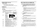
The two active pairs in a 100BASE-TX
network are pins 1 & 2 and pins 3 & 6. Use
only dedicated wire pairs (such as
blue/white & white/blue, orange/white &
white/orange) for the active pins.
1
2
3
6
Twisted
Pair #1
Twisted
Pair #2
Straight Through Cable
1
2
3
6