Install E-FX-HB-xx00 at Site
WARNING: During the site installation, handle the E-FX-HB-xx00 in such a
way that the E-FX-HB-xx00 does not fall. Failure to observe this warning
could result in injury to personnel and/or equipment damage.
NOTE: If E-FX-HB-xx00 is shipped with brackets installed, proceed to step 2.
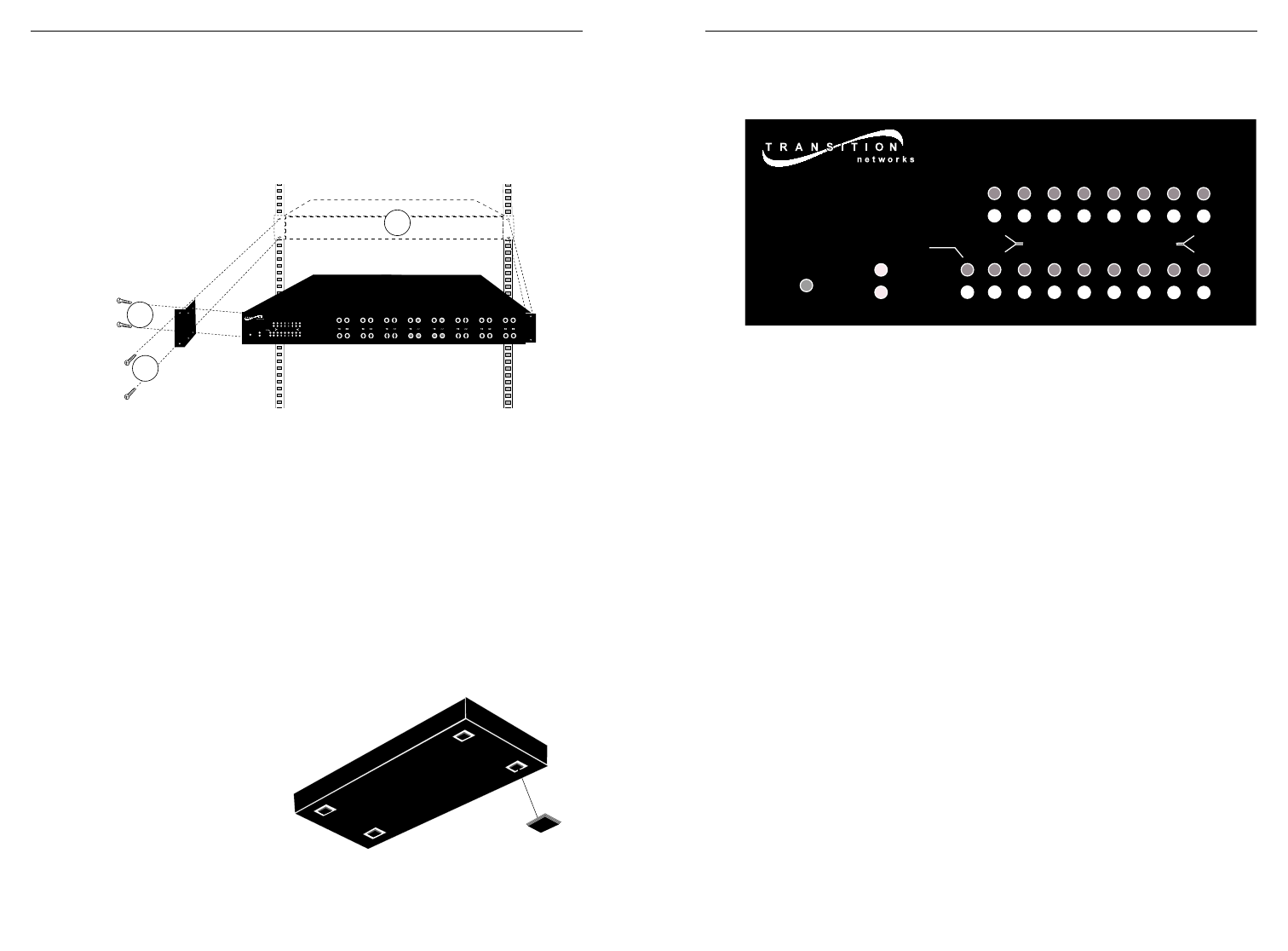
To install the E-FX-HB-xx00 in 19-inch rack cabinet:
1. Remove and retain two (2) screws located at front left side and front
right side of E-FX-HB-xx00 chassis. Install right and left front
brackets (provided) on chassis by installing two (2) retained screws
through each bracket into chassis.
2. Carefully align E-FX-HB-xx00 between 19-inch rack mounting rails.
3. Install E-FX-HB-xx00 by installing two (2) screws through right front
bracket into rack and two (2) screws through left front bracket into
rack, using clip nuts (NOT provided) to secure, if necessary.
To install the E-FX-HB-xx00 on table or other flat surface:
NOTE: Rubber feet are provided.
1. Carefully turn E-FX-HB-xx00 to side.
2. Install four (4) rubber feet:
• Separate rubber feet.
• Remove protective paper
from adhesive
surface on rubber
foot.
• Position and
secure each
rubber foot as
shown.
3. Return E-FX-HB-xx00 to upright position.
OPERATION
Use the status LEDs to monitor E-FX-HB-xx00 operation in the network.
HUB INDICATORS
P(o)W(e)R Steady LED indicates E-FX-HB-xx00 is
connected to external AC power.
COL(lision) Flashing LED indicates network collisions.
G(lobal) F(ault) S(tatus) Steady LED indicates the presence of a
partitioned or isolated port. (A port is
partitioned automatically after a collision
occurs during 60 or more consecutive
attempts to transmit to the port; a port is
isolated if more then two consecutive false
carrier events are received.)
NOTE: The hub unpartitions/unisolates the
port when network traffic becomes normal.
The GFS LED remains illuminated until the
partition/isolation condition is corrected.)
B(ack)B(one) & 100BASE-FX INDICATORS
STAT(us) Steady LED indicates, for each port, a valid
link and no partition or isolation.
Dark LED indicates, for each port, that port
is not linked, is isolated, or is partitioned.
ACT(ivity) Flashing LED indicates, for each port,
reception of data packet(s).
S TAT
PWR
COL
ACT
100BASE-FX
1
2
3
4
5
6
7
8
9
10
11
12
13
14
15
16
ACT
S TAT
GFT
BB
1
3
2
1
3
2
STAT
PWR
4
5
7
6
8
9
11
10
12
13
15
14
16
COL
ACT
100BASE-FX
1
2
3
4
5
6
7
8
9
10
11
12
13
14
15
16
ACT
STAT
GFT
BB


