


Installation
1. Attach a UTP cable from the network to the RJ-45 port.
(Use screened UTP cabling for CISPR 22 class B installation.)
2. Cross-connect the fiber cables: Attach both fiber cables
TX to RX and RX to TX from the fiber network cabling to the
ST-type connectors on the MIL-C2113.
3. Apply power to the unit:
A. Insert the power adapter’s receptacle into the power plug.
B. Insert the power adapter into a wall outlet.
Diagnostic LEDs and Conditions Indicated
There are five LEDs, including power and:
•
•
•
•
•
•
•
•
Link Sentry Configuration
The Link Sentry feature on the MIL-C2113 is configured through
a 4-position DIP switch (refer to Table 1).
The following table displays the Link Sentry dip switch settings needed when the
MIL-C211X is installed in a single media converter environment (not back to back).
Tabl
e 1. Single Converter Link Sentry Settings
1
Fiber TX to RX Link Sentry Disabled
2
3
4
Switch
UP Down
TX/ACTIVE: Receiving packets from the 100BASE-TX port.
FX/ACTIVE: Receiving packets from the 100BASE-FX port.
TX/LINK: An active connection on the 100BASE-TX port.
FX/LINK: An active connection on the 100BASE-FX port.
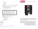
Figure 1. Inside of the MIL-C2113 and
RJ-45 Pinouts
MDI-X/MD
Switch
RJ-45 Female
Connector
SC-Type
Connectors
4
3
2
1
LEDs
4-pin DIP Switch
MDI-X
MDI
1
2
3
4
5
6
8
7
Pin 1= RX+
Pin 2= RX-
Pin 3= TX+
Pin 6= TX-
Pin 1= TX+
Pin 2= TX-
Pin 3= RX+
Pin 6= RX-
MDI-X/MDI Switch
The MDI-X/MDI switch allows for quick configuration
of the 100BASE-TX port. Cables used when the switch is
in the MDI-X position (the “left” position:
For a hub/repeater, use a swap cable (pins are
connected 1 to 3, 2 to 6, 3 to 1, and 6 to 2).
For a workstation/PC, use a straight-through cable
(pins are connected 1 to 1, 2 to 2, 3 to 3, and 6 to 6).
Cables used when the switch is in the MDI position (the
“right” position):
For a hub/repeater, use a straight-through cable (pins
are connected 1 to 1, 2 to 2, 3 to 3, and 6 to 6).
For a workstation/PC, use a swap cable (pins are
connected 1 to 3, 2 to 6, 3 to 1, and 6 to 2).
Multi-modefiber
•
•
•
•
1300nm wavelength
62.5/125 micron diameter
-1
4 dBm launch power
-3
1 dBm receive sensitivity
Si
ngle-modefiber (15Km)
•
•
•
•
1300nm wavelength
9/125 micron diameter
-8 d
Bm launch power
-3
1 dBm receive sensitivity
Single-modefiber (40Km)
•
•
•
•
1300nm wavelength
9/125 micron diameter
-5 d
Bm launch power
-3
4 dBm receive sensitivity
Si
ngle-modefiber (70Km)
•
•
•
•
1300nm wavelength
9/125 micron diameter
-4 d
Bm launch power
-3
7 dBm receive sensitivity
Single-modefiber (100Km)
•
•
•
•
1300nm wavelength
9/125 micron diameter
-3 d
Bm launch power
-3
7 dBm receive sensitivity
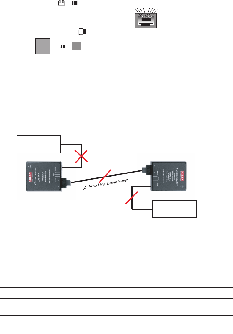
Link Sentry is a troubleshooting feature that allows MiLAN media converters
to monitor link states on both fiber and copper ports in the event of a physi-
cal link down. If a link down is detected, the converter will automatically
notify the end device of the link down by disabling the TX signal of the
neighboring port. (see Figure 2.)
End Node A
End Node B
(1) Link Down Node A
(3) Auto Link Down Node B
Figure 2. Link Sentry Back to Back Configuration
Note: When connecting two MIL-C211X series converters back to
back via fiber, Dip Switches 1 & 2 should be in the “up” and 3 & 4
should be in the “down” position.
Function
Copper to Fiber Link Sentry Disabled
Fiber to Copper Link Sentry Disabled
Fiber TX to RX Link Sentry Enabled
Copper to Fiber Link Sentry Enabled
Fiber to Copper Link Sentry Enabled
Fiber TX link down causes Fiber RX to link down
Reserved, must remain in up position
Copper link down causes Fiber link down
Fiber link down causes Copper link down
N/A
N/A
Note: The MIL-C211X media converters operate at full duplex.
Therefore, when connecting the Copper UTP port, be sure to force the
link partner to 100 Full duplex. Failure to force link partner may result
in a duplex mismatch when connecting to an auto negotiating device.