


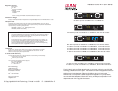

There are four LEDs for both UTP and fiber ports:
4
4
4
4
MDI-X
MDI
1
2
3
4
5
6
8
7
p‹“@Q]rxK
p‹“@R]rxM
p‹“@S]txK
p‹“@V]txM
@@@@@@@@@@@@@@@@@@@p‹“@Q]txK
p‹“@R]txM
p‹“@S]rxK
p‹“@V]rxM
f‹‰š—‡@QN@rjMTU@p‹“”š™˜
D = Duplex; On indicates Full Duplex.
A = Activity; On indicates receiving packets at port.
S = Speed; On indicates rate is 100 Mbs.
L = LINK; On indicates an active connection at port.
4
4
4
4
The MDI-X/MDI switch allows for quick configuration of the
100BASE-TX port. Cables used when the switch is in the MDI-X
position (the "left" position:
For a hub/repeater, use a swap cable (pins are
connected 1 to 3, 2 to 6, 3 to 1, and 6 to 2).
For a workstation/PC, use a straight-through cable
(pins are connected 1 to 1, 2 to 2, 3 to 3, and 6 to 6).
Cables used when the switch is in the MDI position (the"right"
position):
For a hub/repeater, use a straight-through cable (pins
are connected 1 to 1, 2 to 2, 3 to 3, and 6 to 6).
For a workstation/PC, use a swap cable (pins are
connected 1 to 3, 2 to 6, 3 to 1, and 6 to 2).
1. Make any configuration changes to the module DIP switch settings.
2. Remove cover plate from MCS chassis.
3. Slide module into a slot through the card guides.
4. Firmly seat module into card-edge connector.
5. Secure module with thumbscrews located on module faceplate.
6. Plug in network connections.
Note: There is no need to power off the Media Conversion System.
To maximize the fiber cable distance, use one meter of CAT 5 UTP cable
when connecting directly to a node (subject to fiber budget of 16dBm and
collision domain restrictions). In full-duplex environments, use up to
100m of CAT 5 UTP and:
4 2Km of multi-mode optical fiber for MIL-S3412, S3413, S3414
4 15Km of single-mode optical fiber for MIL-S3413-15, S3414-15
4 40Km of single-mode optical fiber for MIL-S3413-40
4 70Km of single-mode optical fiber for MIL-S3413-70
4 100Km of single-mode optical fiber for MIL-S3413-100
Multi-mode fiber (2Km)
4 1300nm wavelength
4 62.5/125 micron diameter
4 Launch power: -19dBm minimum
4 -31dBm receive sensitivity
Single-mode fiber (40Km)
4 1300nm wavelength
4 9/125 micron diameter
4 Launch power: -4dBm minimum
4 -34dBm receive sensitivity
Single-mode fiber (100Km)
4 1550nm wavelength
4 9/125 micron diameter
4 Launch power: 1.8dBm minimum
4 -37dBm receive sensitivity
Single-mode fiber (15Km)
4 1300nm wavelength
4 9/125 micron diameter
4 Launch power: -15dBm
4 -31dBm receive sensitivity
Single-mode fiber (60Km)
4 1550nm wavelength
4 9/125 micron diameter
4 Launch power: 0dBm minimum
4 -37dBm receive sensitivity
Up Position
Down Position
Switch 1
Auto-Negotiation
Enable Port 1
Disable Port 1
Switch 3
Speed
100Mbs Port 1
10Mbs Port 1
Up Position
Down Position
Switch 5
Duplex
FDX Port 1
HDX Port 1
Switch 6
Duplex
FDX Port 2
HDX Port 2
Switch 4
Speed
100Mbs Port 2
10Mbs Port 2
Switch 7
Packet size
1518 Bytes
1522 Bytes
Switch 2
Auto-Negotiation
Enable Port 2
Disable Port 2
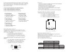
Speed and Half/Full Duplex or Auto Negotiation may be manually
selected using the seven-position DIP switch.
All switches must be in the up position to utilize SNMP feature selection.
Fiber ports operate at 100Mbs only.
Port 1 is on the left. Port 2 is on the right.
MDI-X/MDI
Switch
RJ -45
Connector
LEDs
6
7
5
4
3
2
1
7- pin DIP Switch
MDI-X/MDI
Switch
RJ -45
Connector
M DI-X / M DI Sw itch (Figure 1 )
Insta lla tion
Dia gnostic LEDs a nd Conditions Indica ted
Dip Sw itch Fea tures (Figure 2 )
Figure 2. Inside of the M IL-S3 41 0