6
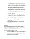
5. AC Fault LED (Yellow/Red): Yellow when commercial input voltage is lost or too
low or input frequency shifts drastically and unit switches to inverter mode. Red
when commercial input voltage is
too high and unit switches to inverter
mode
.
Both stay on until fault is cleared. Off as long as commercial voltage is present
and in range, and frequency is stable.
6. Battery Status LED (Yellow/Red): Yellow at low battery warning. Red at low
battery cutoff for one (1) second. Off otherwise.
7. Overload LED (Red): On when inverter shuts down because of unit overload or
because input frequency is far out of range, off otherwise. Overload LED stays
on until unit power switch is turned off and back on with conditions corrected.
8. Fuse/Breaker Fault LED (Red): On when AC fuse (AT650, AT800 or AT2300) is
blown or AC Breaker (AT1200 or AT1600) is tripped, off otherwise.
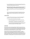
9. Output Receptacles, 120VAC units: 4 NEMA 5-15R receptacles on all units
except AT2300. AT2300 has 6.
10. Power Cord, 120VAC units: AWG 18/3 (AT650 and AT800) or AWG 14/3
(AT1200 and AT1600) SJT with NEMA 5-15P Plug (standard) or AWG 12/3 SJT
(AT2300) with NEMA L5-30P Plug.
11. Input Fuse Holder/Breaker: At650, AT800 and AT2300 units use fuse and fuse
holder at input. AT1200 and AT1600 units use AC circuit breaker at input.
12. LAN Communications Port (DB9 Female): Standard on all units.
13. Cooling Fan: Models AT1200, AT1600 an AT2300 only. Smaller models are
convection cooled.
14. Audible Alarm (Internal): Sounds twice every two seconds in normal inverter
mode after an initial five (5) second delay; sounds four (4) times per second at
low battery warning.
GS MODELS
Each GS model is the same as the comparable AT series model except for power plugs and
receptacles. GS units use global sockets (2 on GS650 and GS800, and 4 on GS1200 and larger
units) on all models instead of the receptacles shown in unit pictorials. These models use an
IEC320 power cord socket with user selectable international cord sets.
INSTALLATION AND PRELIMINARY TESTING
Ensure that the UPS power switch is off ("0" position) and no load is connected to the
UPS output receptacles.
Plug the UPS power plug into a grounded commercial power receptacle with proper
supply voltage and frequency for the specific UPS model under test. For GS models,
first plug the cord set into the UPS IEC320 socket.


