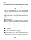
◆ When using an isolation tranasformer, ensure that the load is balanced.
◆ When using #6 AWG wire 2 in. are required for wire bending space opposite the terminals. 1 1/2 in. for #8 AWG.
3 in. for #3 AWG and #4 AWG. 3 1/2 in. for #2 AWG.
◆ For 6KVA output configuration #1, #2, #3, #4, #5, #6, and #7 use #6 AWG, 75ºC copper wire. For 10KVA
output voltage configuration #1, use #2 AWG,115ºC copper wire. For configurations #2, #3, #4, #5, and #6 use
#6 AWG, 75ºC copper wire.
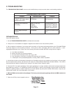
Tightening torque for pressure wire connectors having screws
Size of wire that is to be used
for connection of the unit
AWG/kcmil
8
6-4
3
2
mm
2
8.4
13.3-21.2
26.7
33.6
Tightening torque, pound-inches (N-m)
Slot width - 0.047 in.
(1.2mm) or less, and
slot length - 1/4 inch
(6.4mm) or less
25 (2.8)
35 (4.0)
35 (4.0)
40 (4.5)
Slot width - over
0.047 in. (1.2mm)
and slot length - 1/4
inch (6.4mm)
25 (2.8)
45 (5.1)
50 (5.6)
50 (5.6)
Hexagonal head - external
drive socket wrench
Split-bolt
connectors
80 (9.0)
165 (18.6)
275 (31.1)
275 (31.1)
Other
connections
75 (8.5)
110 (12.4)
150 (16.9)
150 (16.9)
Slotted head No. 10 (4.7mm) and Larger
Page 9
Maximum current
rating (amperes)
60
90
100
150
Maximum size of
equipment grounding or
bonding conductor AWG
10
8
8
6
Minimum size of
grounding electrode
conductor AWG
8
8
6
6
Maximum size of
equipment grounding or
bonding conductor AWG
8
8
6
6
Size of grounding electrode conductors (copper wire)
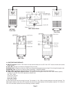
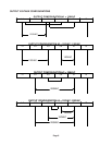
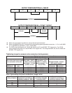
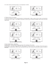
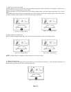
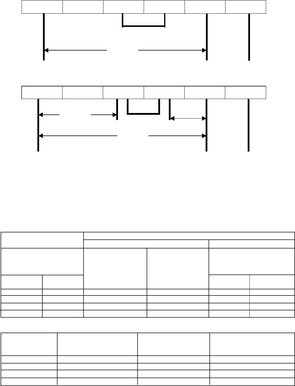
OUTPUT CONFIGURATION #5 = 240VAC
L1 L2 L3 L4 N G
240VAC
OUTPUT CONFIGURATION #6 = 120VAC / 240VAC
L1 L2 L3 L4 N G
120VAC 120VAC
240VAC


