


Extron • System 4
xixi
xixi
xi
Switcher Series • User’s Manual • P/N 68-401-02 Rev. C
Configuration and Connections
Mitsubishi Installation
Page 3
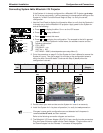
RGBHV 5 BNC
15-Pin
Male
9-Pin Female
SY-VGA
26-173-01
ComAdapter
26-475-01 "G"
15-Pin Male
G
OUTPUT
PJ COMM
RS 232
AUDIO AUDIO AUDIO AUDIO AUDIO
H/HV
R/C G/Y BR/C G/Y B
V
INPUT 4
H/HV V
R/C G/Y B
INPUT 3
H/HV V
R/C G/Y B
INPUT 2
H/HV V
R/C G/Y B
INPUT 1
H/HV V
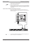
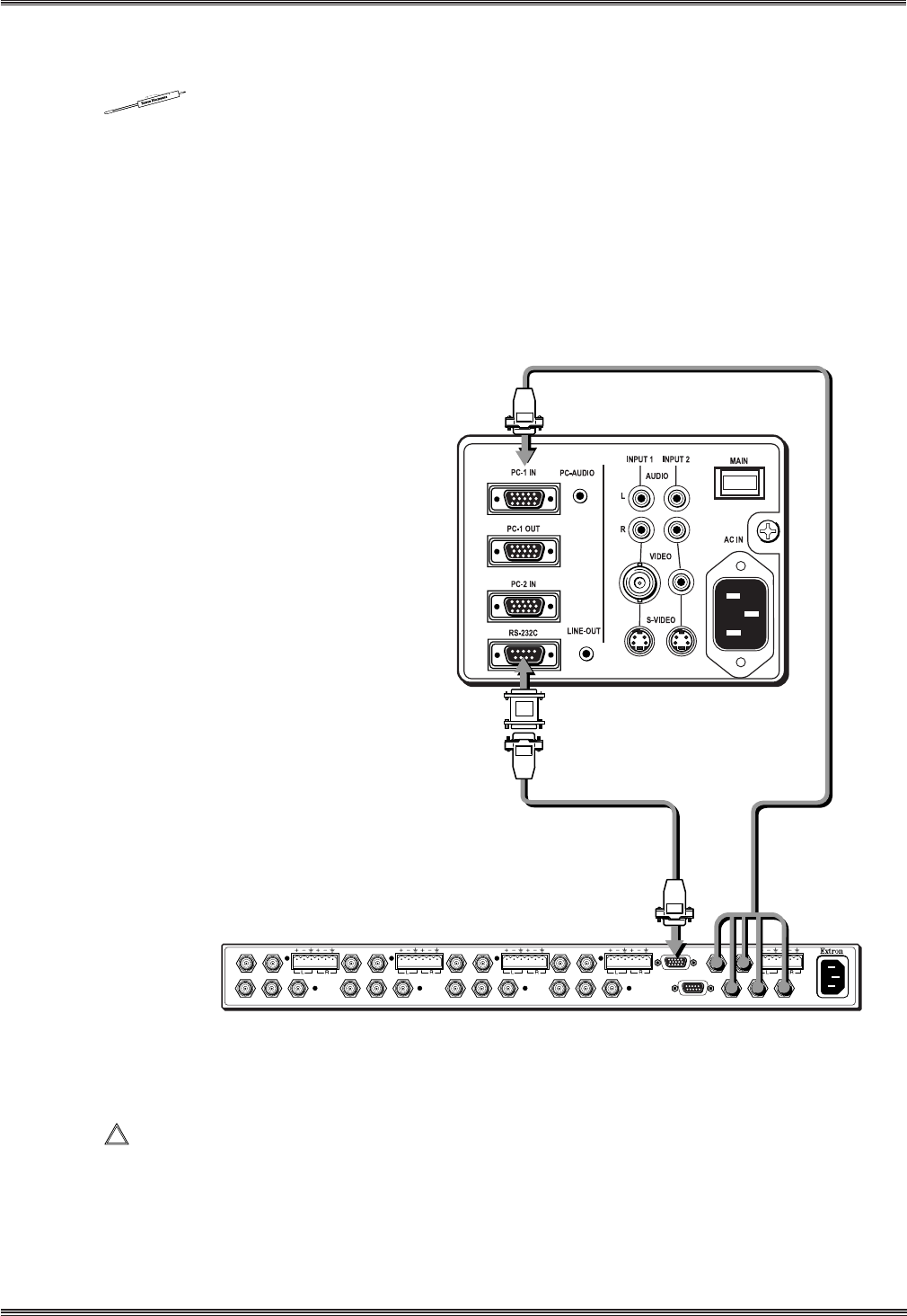
6. Plug the 15-pin HD connector of the Projector Communications Extension cable
into the PJ Comm port on the System 4xi.
______ Secure all of the connector screws.
7. Plug the (4 or 5) BNC connectors from one end of the (user-supplied) RGBS/HV
cable onto the System 4xi output. Connect the 15-pin connector on the other end
of the RGBS/HV cable to the PC-1 Input connector on the Mitsubishi LVP-X100
connector panel.
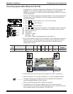
System 4xi Series – Mitsubishi LVP-X100 Projector Connections
Use the illustration below as a guide when connecting the System 4xi to a
Mitsubishi LVP-X100 Projector. Refer to Mitsubishi LVP-X100 documentation to
continue the installation.
____________ In a rack mount, do NOT allow the weight of the cables to be supported by the
System 4
xi
. See page 2-5 for cabling guidelines.