


8
CONNECTIONS
OTHERS
PRECAUTIONS
FEATURES
PREPARATION
TROUBLE-
SHOOTING
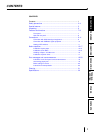
CONTENTS
AC LINE
6
4
1
3
3
2
5
5
11
11
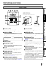
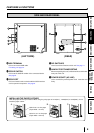
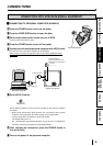
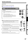
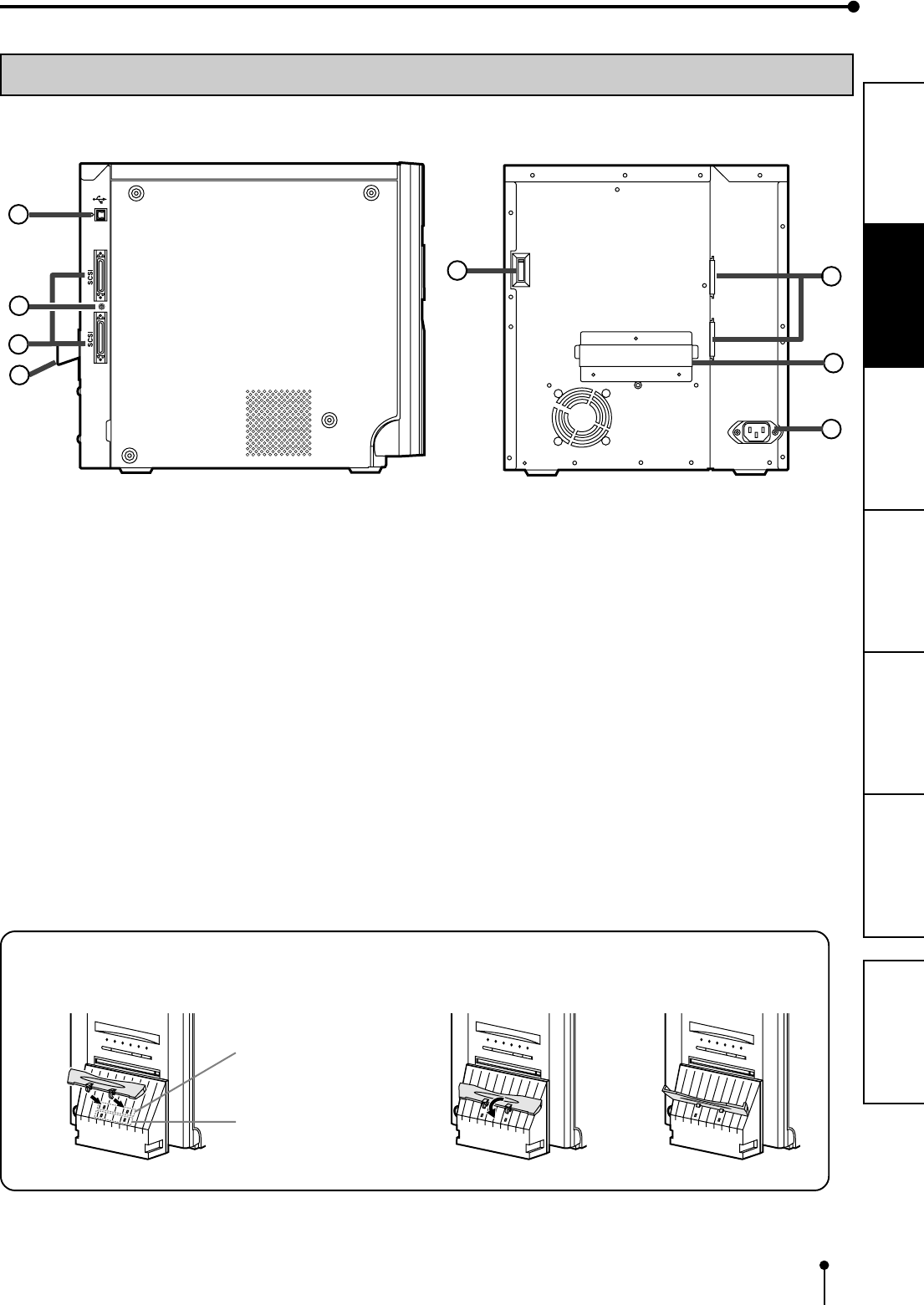
1 USB TERMINAL
Use to connect the USB cable.
For setting, see page 10.
22
22
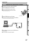
2 SCSI ID SWITCH
Use to set the SCSI ID number of the connected device.
See page 9.
33
33
3 SCSI PORT
Use to connect this unit to a device with the SCSI interface
such as personal computers. See page 9.
SIDE AND REAR PANEL
FEATURES & FUNCTIONS
44
44
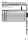
4 DIP SWITCHES
Use to set various functions of this unit. See page 11.
55
55
5 HANDLE FOR TRANSPORTING
When transporting this unit, hold this handle and the lower
front part of this unit.
66
66
6 POWER SOCKET (AC LINE)
Use to connect the provided power cord. Insert the cord
firmly.
(LEFT SIDE)
(REAR)
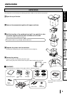
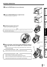
INSTALLING THE PAPER CATCHER
Hook the paper catcher by its latches. When using the print paper of 13x18(5x7”), 15x20(6x8”) or 15x23(6x9”), do not
install the paper catcher.
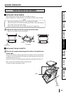
A. B. C.
Holes for 10 x 15 size paper
(Paper width : 152 mm)
Holes for 9 x 13 size paper
(Paper width : 127 mm)