


Series HMI Connection Manual
Definition of PLC Read/Write Address
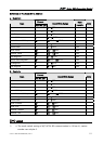
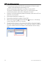
a. Registers
V1.02 Revision November, 2011 111
Format
Type
Word No. (n)
Read/Write Range
Data
Length
Note
Xn X0 – X7FF Input Word 3
Yn Y0 – X7FF Output Word 3
Bn B0 – BFFF Link Relay Word 3
Mn M0 – M8176 Internal Relay Word 3
SMn SM9000 – SM9240 Special Internal Relay Word 4
Ln L0 – L2032 Latch Relay Word 3
Fn F0 – F2032 Annunciator Word 3
TNn TN0 – TN999 Timer Value Word
CNn CN0 – CN999 Counter Value Word
Dn D0 – D8191 Data Register Word
SDn SD9000 – SD9255 Special Data Register Word
Rn R0 – R8191 File Register Word
Wn W0 - WFFF Link Register Word
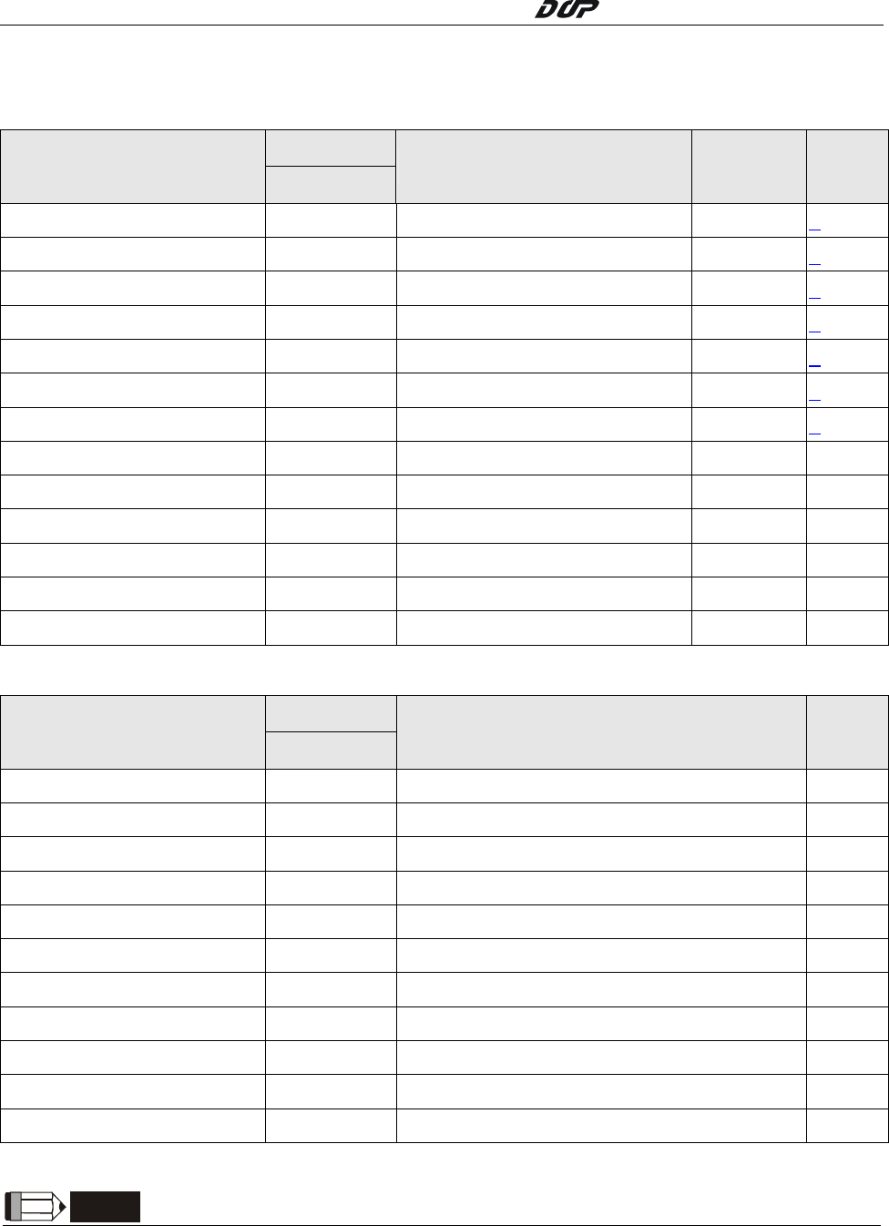
b. Contacts
Format
Type
Bit No. (b)
Read/Write Range Note
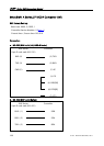
Input Xb X0 – X7FF
Output Yb Y0 – Y7FF
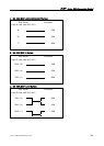
Link Relay Bb B0 – BFFF
Internal Relay Mb M0 – M8191
Special Internal Relay SMb SM9000 – SM9255
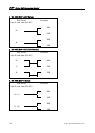
Latch Relay Lb L0 – L2047
Annunciator Fb F0 – F2047
Timer Contact TSb TS0 – TS999
Timer Coil TCb TC0 – TC999
Counter Contact CSb CS0 – CS999
Counter Coil CCb CC0 – CC999
NOTE
1) a. The mode switch setting of AJ71UC24-R2 communication is 4 (Form 4), station
number can only be 0.