


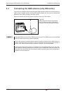
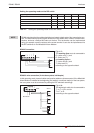
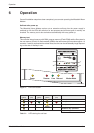
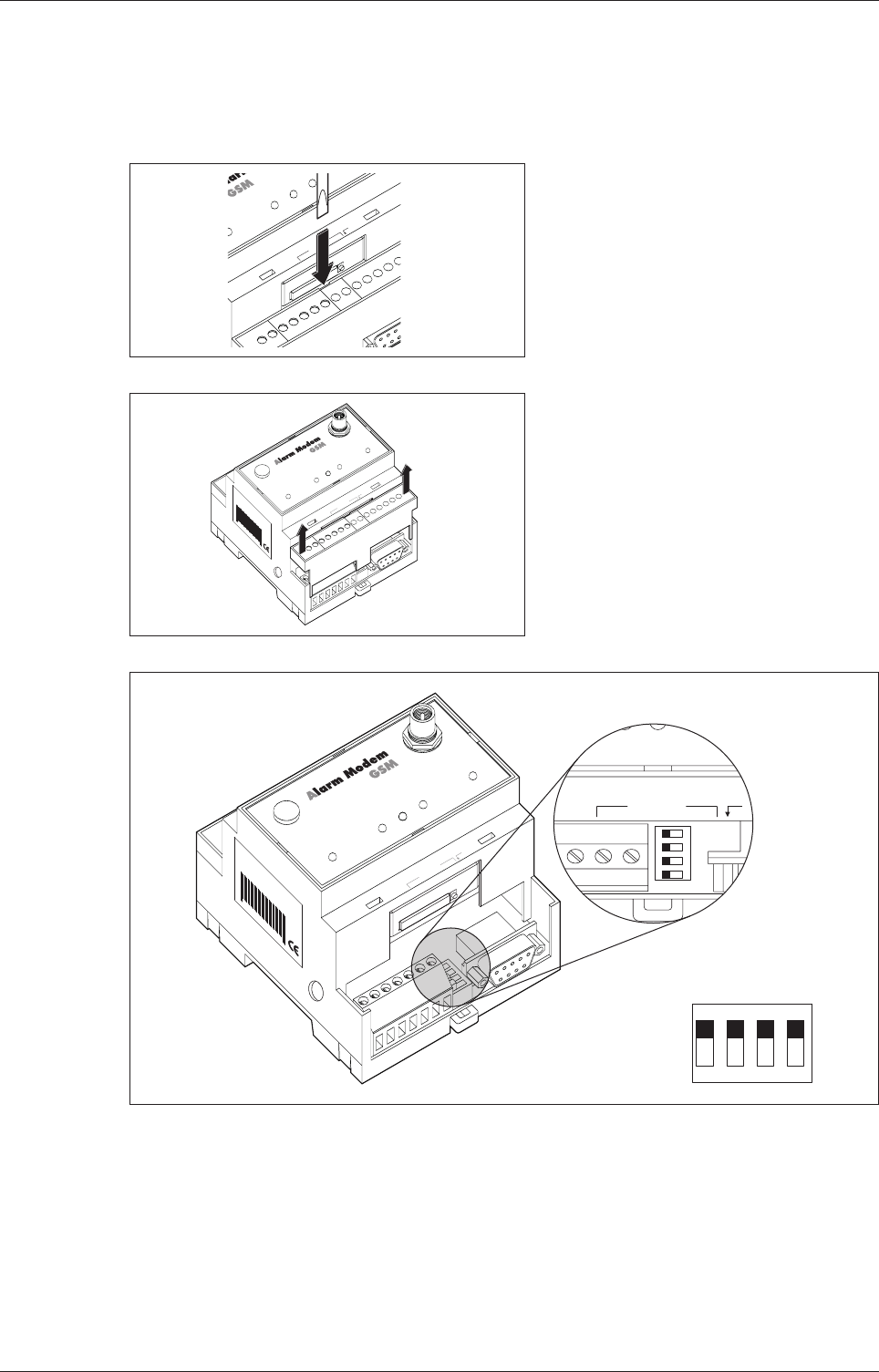
Access to the DIP switches
A DIP switch is provided for selecting the operating mode at the RS485/422 interface. This is
located on the right of the COM2 connection terminal and is accessible after the cover is
removed.
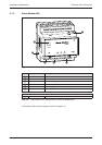
Interfaces RS485 / RS422
Mitsubishi Alarm Modem 4-3
-
+
COM1
(R
S4
COM2
(RS422 / 485)
P
ower
Process
Line
Data out
DC
1
0...30V
SIM-Card
Pus
h
R+
R-
-T
+T
(0V)
Bus
Config.
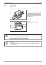
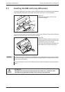
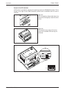
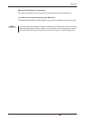
Fig. 4-4:
Put a screwdriver (blade width 3mm) into
the small slit and gently rotate the screw
-
driver.
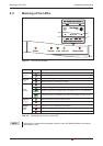
HG47
Tixi Alarm Modem GSM
xxxxx Xxxxx+Xxxx
xx - xx X XX, xxx. X.X X
027954541034
Service
Power
Process
Line
Data out
Modem Mode
Antenna
-
+
COM1
(RS485)
COM2
(RS422 / 485)
DC
1
0...30V
SIM-Card
Push
R+
R-
-T
+T
(0V)
Bus
Config.
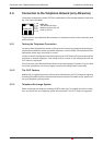
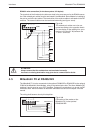
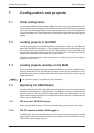
Fig. 4-5:
The terminal cover snaps off from the
case with an audible click and may be
removed.
Process Line Data out
1
ON
DIP
2
3
4
SIM-Card Pu
Mitsubishi Alarm Modem GSM
xxxxx Xxxxx+Xxxx
xx - xx X XX, xxx. X.X X
027954541034
Service
DC
10...30V
Power
Process
Line
Data out
Modem Mode
Antenna
SIM-Card
Push
1
ON DIP
234
1
0
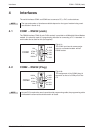
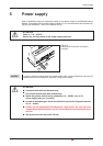
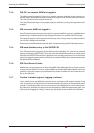
Fig. 4-6: Position of the DIP switches under the terminal cover