


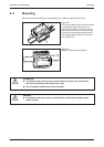
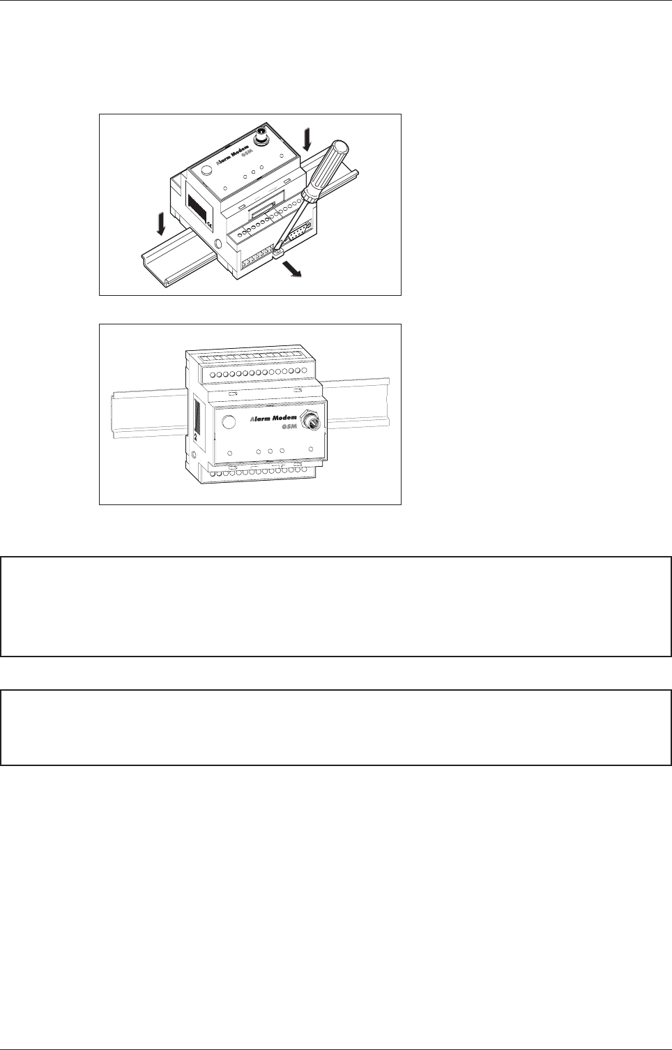
3.3 Mounting
Mount the modem by pushing or snap fitting it onto a DIN rail (top-hat rail 35 mm).
E
ATTENTION:
P
DANGER:
Installation and Mounting Mounting
Mitsubishi Alarm Modem 3-4
-
+
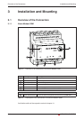
COM1
(RS485)
COM2
(RS422 / 485)
Mitsubishi Alarm Modem GSM
xxxxx Xxxxx + X xxx
xx - xx X XX, xxx.X.X X
027954541034
Service
Power
Process
Line
Data out
Modem Mode
Antenna
DC
1
0...30V
SIM-Card
Pus
h
R+
R-
-T
+T
(0V)
Bus
Config.
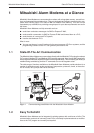
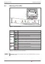
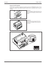
Fig. 3-4:
Pull out the black tab on the device using
a screwdriver and so the device can
snap fit to the DIN rail. You can remove
thedevicefromtherailinthesameway.
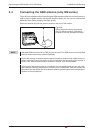
Ensure that the retaining machanism of
the modem snaps cleanly and securely
into the DIN rail.
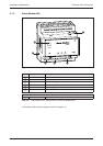
Service
Antenna
Power
Process
Line
Data out
Modem Mode
027954 541034
-
+
COM2
(RS232)
COM1
(RS232)
SIM-Card
Pus
h
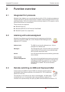
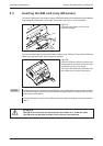
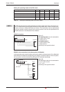
Fig. 3-5:
Modem mounted on the DIN rail
b
The device must only be used in rooms that are dry and clean. Protect the
device from humidity, water splashes or heat.
b
Do not subject the device to severe vibration.
b
The device must not be used in environments containing flammable gases,
fumes or dust.