


3
zDifferences from QJ71LP21-25
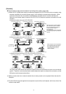
The QJ71LP21S-25 has the same function and performance as the QJ71LP21-25. Therefore, the program for
the QJ71LP21-25 is available for the QJ71LP21S-25.
However, the QJ71LP21S-25 requires two I/O slots while the Q71LP21-25 requires only one I/O slot.
[Performance Specifications]
Item QJ71LP21S-25
LX/LY 8192 points
LB 16384 points (In MELSECNET/10 mode: 8192 points)
Maximum number
of link points per
network
LW
16384 points (In MELSECNET/10 mode: 8192 points)
Maximum number of link points per
station
((LY + LB) /8 + (2 × LW) ≤ 2000 bytes
Communication speed 25 Mbps/10 Mbps (Selectable by mode switch)
Number of connectable stations per
network
64 stations (control station: 1, normal station: 63)
Connection cable Optical fiber cable *1
Overall distance 30 km (98430 ft.)
25Mbps
Sl optical cable:200 m (656.2 ft.)
H-PCF optical cable :400m (1312.4 ft.)
Broad-band H-PCF optical cable :1 km (3281 ft.)
QSl optical cable:1 km (3281 ft.)
Distance between
stations
10Mbps
Sl optical cable: 500 m (1640.5 ft.)
SI type H-PCF optical cable :1 km (3281 ft.)
Broad-band H-PCF optical cable :1 km (3281 ft.)
QSl optical cable:1 km (3281 ft.)
Maximum number of networks 239 (Total including number of remote I/O networks)
Maximum number of groups 32 (In MELSECNET/10 mode: 9)
Transmission path format Duplex loop
Communication method Token ring
Synchronous method Frame synchronous method
Encoding method NRZI (Non Return to Zero Inverted) code
Transmission format Conforms to HDLC (Frame type)
Error control system
Retries based on CRC (X
16
+X
12
+X
5
+1) and timeover
RAS function
y Loopback function due to error detection and cable breakage
y Link line self-diagnostic function
y Prevention of system failure by switching to alternative control station
y Error detection using special relays and registers
Transient transmission
y N-to-N communication (monitoring, program up/downloading, etc.)
y Various send/receive instructions from sequence programs
(ZNRD/ZNWR,SEND/RECV,RECVS,READ/WRITE,SREAD/SWRITE,
REQ,RRUN/RSTOP,RTMRD/RTMWR)
y Send function by addressing to channel number of 1 to 8
Special cyclic transmission function y Low-speed cyclic transmission function
No. of occupied I/O points 48 points (I/O assignment: first 16 points as empty, last 32 points as intelligent) *2
Voltage 20.4 to 31.2 V DC
Current 0.20 A
Terminal screw size M3 screw
Applicable solderless
terminal
R1. 25-3
Applicable wire size
0.3 to 1.25 mm
2
External
supply
power
Tightening torque 42 to 58Nycm
Internal current consumption (5 VDC) 0.55 A
Weight 0.20kg
*1: For conventional optical fiber cable (A-2P- ), the distance between stations varies with the type L and H.
*2: Two I/O slots are occupied.
The head I/O address should be the number added on 10H to the head address of installed slot, because the
first slot occupies 16 points as a vacant and the second slot occupies 32 points for the automatic I/O
assignment. It is available to assign zero for the first slot.
(Example)
When installing the module to slot 0, set 10
H to “Start I/O No.”
(When 0 point is set for slot 0 in the I/O assignment, set 0
H to “Start I/O No.”)