


32
OPERATING PROCEDURE
PHOTOS & ILLUSTRATIONS
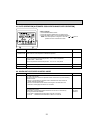
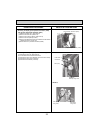
7. Removing the panel
(1) Remove the air intake grille and the filter. (See Figure 1)
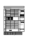
(2) Disconnect the connector CNV (White/20P).
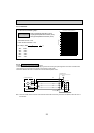
Corner panel (See Figure 2)
(3) Remove the corner screw.
(4) Slide the corner panel to the direction of the arrow 1, and
remove the corner panel.
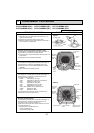
Panel (See Photo 4, 5)
(5) Remove the 2 screws from the panel which fixes to the oval
holes.
(6) Rotate the panel a little to come to the bell shaped hole
where the screw is large and remove the panel.
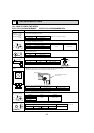
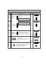
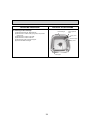
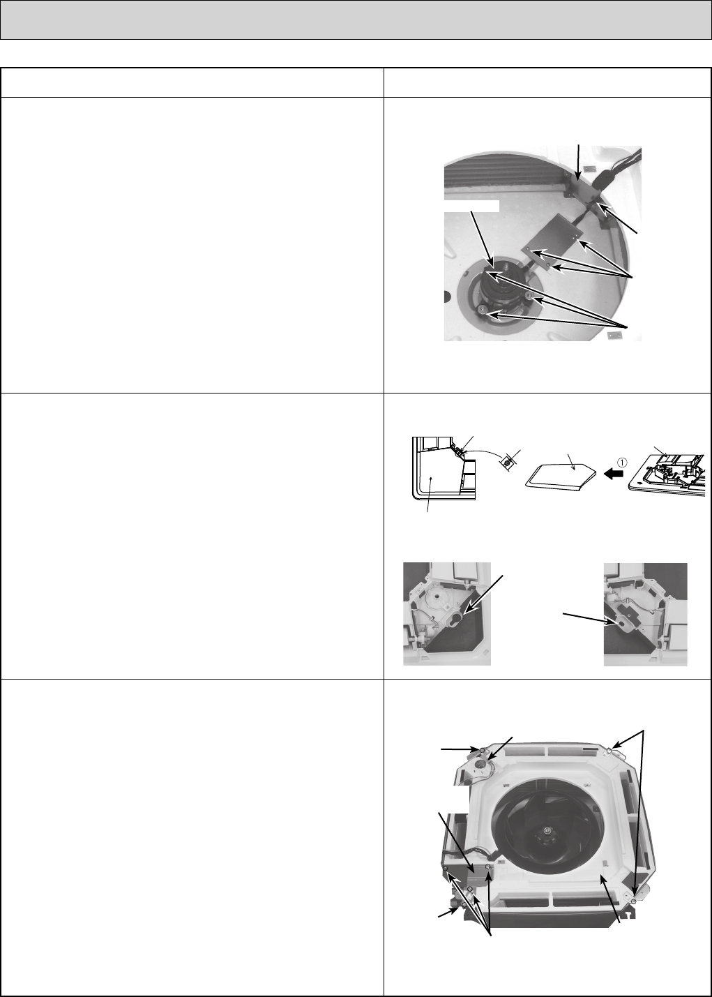
6. Removing the fan and fan motor (MF)
(1) Remove the electrical box. (See Photo 2)
(2) Remove the bell mouth (3 screws). (See Photo 2)
(3) Remove the turbo fan nut.
(4) Pull out the turbo fan.
(5) Remove the wire cover (3 screws).
(6) Remove 2 wiring clamps.
(7) Disconnect the connector of the fan motor (CNMF).
(8) Remove the 3 nuts and washers and rubber mounts of the
fan motor.
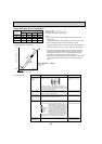
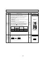
8. Removing the drain pan
(1) Remove the air intake grille and the filter. (See Figure 1)
(2) Remove the 2 screws from the electrical box cover.
(3) Disconnect the connectors. (Refer to 4.)
(4) Remove the panel. (See Photo 4, 5)
(5) Remove the electrical wiring service panel (3 screws).
(6) Remove the drain pump wire cover (1 screw).
(7) Remove the electrical box. (See Photo 2)
(8) Remove the bell mouth. (See Photo 2)
(9) Remove the 4 screws and pull out the drain pan.
w Pull out the left and right of the pan gradually.
Be careful not to crack or damage the pan.
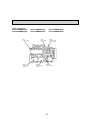
Figure 2
Bell shaped hole
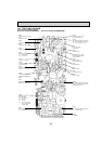
Coil plate
Wire cover
fixing screw
Clamp
Fan motor
Nut
Washer
Rubber mount
Screw
Screw
Corner panel
Corner panel
Panel
Detail
Photo 4
Photo 5
Oval hole
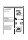
Photo 6
Drain pan
fixing screw
Drain pan
fixing screw
Drain pump wire cover
Drain pan
Electrical wiring
service panel
Drain pan
fixing screw
Electrical wiring ser-
vice panel fixing screw
Photo 3