


33
OPERATING PROCEDURE
PHOTOS & ILLUSTRATIONS
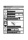
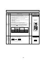
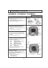
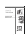
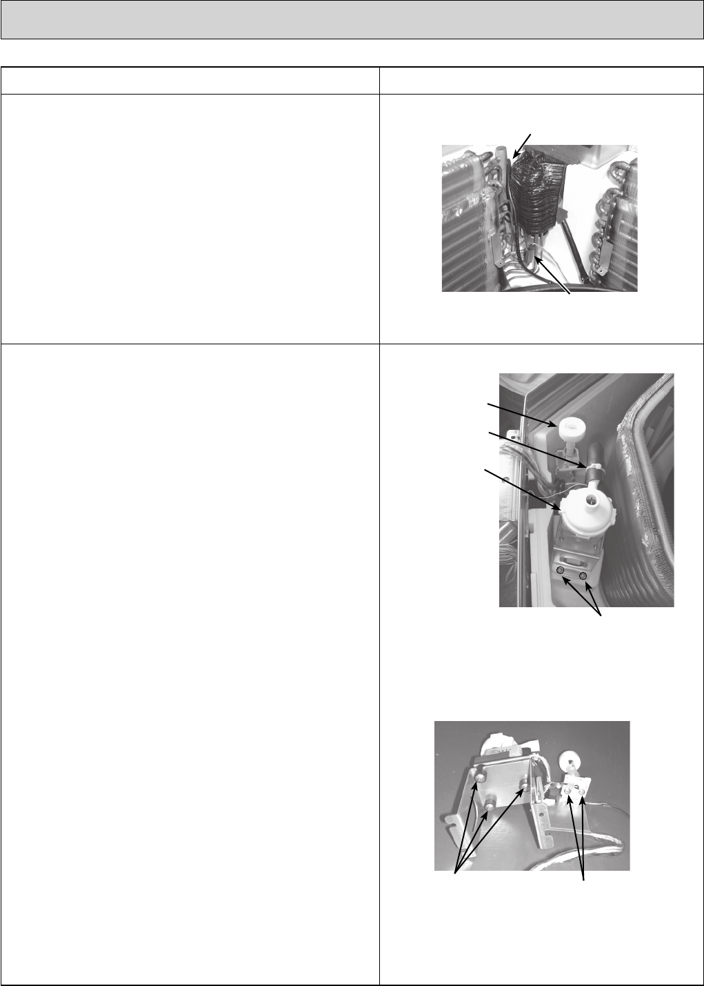
10 Removing the drain pump (DP) and float switch (FS)
(1) Remove the drain pan. (See Photo 6)
(2) Cut the hose band and remove the hose.
(3) Remove the drain pump assembly (3 screws and 2 hooks).
(4) Remove the drain pump (3 screws).
(5) Remove the float switch (2 screws).
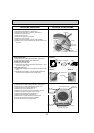
Photo 8
Photo 9
Drain pump
Hose band
Float switch
Drain pump
assembly fixing screw
Drain pump
fixing screw
Float switch
fixing screw
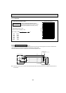
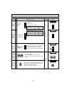
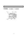
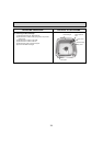
9. Removing the liquid pipe temperature thermistor (TH22)
and gas pipe temperature thermistor (TH23)
(1) Remove the drain pan. (See Photo 6)
(2) Remove the turbo fan. (Refer to 6)
(3) Remove the 2 wiring clamps. (See Photo 3)
(4) Remove the coil plate (2 screws).
(5) Remove the thermistors which are inserted into the holders
installed to the thin copper pipe.
(6) Disconnect the 4-pin white connector (CN44).
Photo 7
Gas pipe temp. thermistor (TH23)
Liquid pipe temp. thermistor (TH22)