


Connection and Operation
S-VIDEO
VIDEO AUDIO
INPUT-1
HIGH-DEFINITION INTERFACE
RG B H
HDTV VIDEO
VIDEO AUDIO
HDTV CONTROL
IR
HOME
THEATHER
IR/
G LINK
ACTIVE A/V
NETWORK
HDTV AUDIO
MONITOR
OUTPUT
PIP
AUDIO
OUTPUT
INPUT-2
DVD VIDEO
INPUT-3
VL
(MONO)
R
VL
(MONO)
R
L
(MONO)
R
L
(MONO)
R
Y
ANT-A ANT-B
LOOP
OUT
Cr Cb
V
PHONE JACK
RF
YL L
Pb RR
Pr
REMOTE VIDEO VIDEO
AUDIO AUDIO
S-VIDEO
CONTROL
VCR
AUDIO OUT
OUT TO TV
IN FROM ANT SATELLITE IN
CAUTION
RISK OF ELECTRICAL SHOCK
DO NOT OPEN
CH 3
CH 4
DIGITAL
TV Back Panel
Adapter Module
RGB-CV10
Back Panel
HDTV Receiver Back Panel
To AC wall
outlet
HDTV VIDEO OUT HDTV VIDEO IN
RGB HV Y PrPb
DC13.2V
HDTV CONTROL
1
2
3
6
4
5
1
2
3
4
5
6
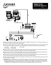
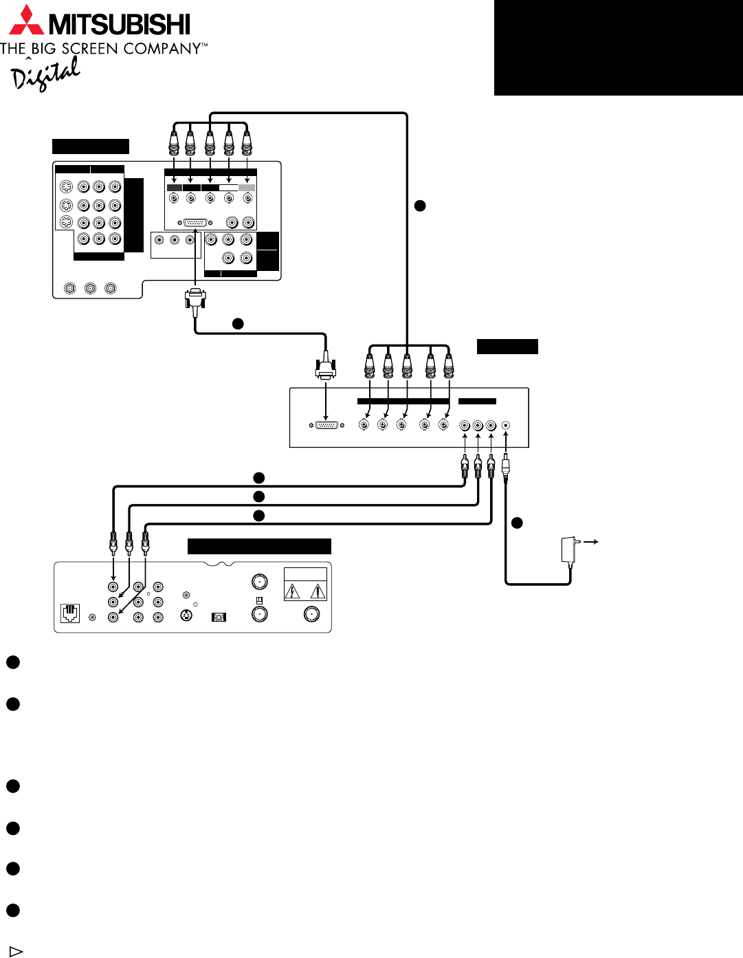
Connect one end of the HDTV control cable to the HDTV CONTROL terminal of the TV. Connect the other end to
the HDTV CONTROL terminal of the Adapter Module.
Following the color codes, connect the 5-in-1 BNC cable to the HDTV VIDEO terminals of the TV. Connect the other
ends to the HDTV VIDEO OUT terminals of the Adapter Module. The terminal ends are color-coded as follows:
R-red cable G-green cable B-blue cable
H-white cable V-yellow cable
Connect one end of the Component Video cable or one end of the three video cables to the Y terminal of the Set Top
Box. Connect the other end to the HDTV VIDEO IN Y terminal of the Adapter Module.
Connect one end of the Component Video cable or one end of the three video cables to the Pb terminal of the Set Top
Box. Connect the other end to the HDTV VIDEO IN Pb terminal of the Adapter Module.
Connect one end of the Component Video cable or one end of the three video cables to the Pr terminal of the Set Top
Box. Connect the other end to the HDTV VIDEO IN Pr terminal of the Adapter Module.
Connect the DC 13.2V adapter cable of the AC adapter to the DC13.2V jack of the Adapter Module and connect its AC
plug into the AC wall outlet.
Important: When a 1080i signal is input, the SIGNAL indicator on the front panel of the Adapter Module illuminates
and signal isoutput to the TV. When a signal other than 1080i is input, the SIGNAL indicator on the front panel of the
Adapter Module flashes and no signal is output to the TV. When there is no signal, the connection is incomplete or the
TV POWER is OFF, the SIGNAL indicator on the front panel of the Adapter Module does not illuminate.
RGB-CV10
ADAPTER MODULE
Page 1 2 3