


5
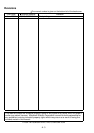
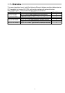
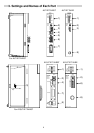
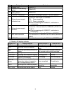
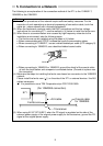
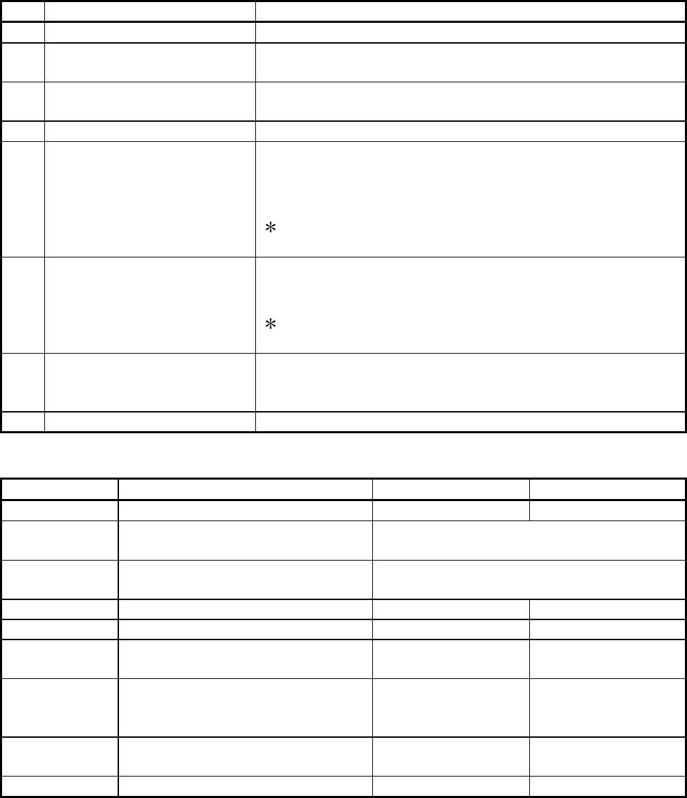
No Designation Contents
1) Display LED Refer to (1)
2)
Operation mode setting
switch
Refer to (2)
3)
Exchange condition
setting switch
Refer to (3)
4) 10BASE-T connector Connector for connecting the E71 to the 10BASE-T.
5)
External power supply
indicator lamp
Lamp for verifying if power is being supplied to the
transceiver when used as 10BASE5.
ON: Power supplying
OFF: Power not supplied
When connecting with 10BASE-T, verification is
unnecessary.
6)
External power supply
terminal
Power source terminals for power source supply to the
transceiver in the connection of 10BASE5. (14.08 V to
15.75 V)
When connecting with 10BASE-T, verification is
unnecessary.
7) AUI cable connector
Connector for connecting the E71 to the 10BASE5.
(For connection of 10BASE5-use AUI cable (transceiver
cable))
8) 10BASE2 connector Connector for connecting the E71 to the 10BASE2.
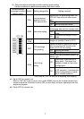
(1) Display LED display contents
Display LED Display contents When lamp is lit Lamp is not lit
RUN Normal operation display Normal Error
RDY Exchange ready end display
Starts flashing when On-line Operations
begin
BSY
Exchange processing executing
display
Turns on when exchange processing
with remote node is being executed.
SW.ERR. (For system) — —
COM.ERR. Exchange error detection display Exchange error Normal
CPU R/W
Exchange processing executing
with PLC CPU display
Exchanging Not exchanging
BUF1 to
BUF8
Display of communication line
connection status of connection
No.n corresponding to BUFn.
Open completed Closed status
TEST Self diagnostic executing display
Self diagnosis
executing
Self diagnosis
completed
TEST ERR. Self diagnosis results display Error Normal