


8
P.B.
L.B.
TB1
PE
L1
L2
Main Power Switch 3A
Unit Body
Unit Body
CN31
313
AC250V
2A T
ZNR2
F
1
T2
CN33
DSA1
ZNR1
Unit Body
7
3
1
5
CN71
SWL
(Service
Switch)
(Service
LEDL
LED)
1
3
4
3
2
1
5
6
CN45
T1
CN65
2
1
CN21
3
1
CN32
1
2
3
4
CNL12
CN605
5
4
3
2
1
LED402
(5VM)
LED502
(3150RST)
6
4
3
2
1
M-NET
Power Supply
CN40
(WDT)
LED009
LED201
CN41
(18007RST)
SW71
(Termination Switch)
12
ON
OFF
312
TO M-NET transmission line
(Centralized control line)
CNS3
AB
TB2
13
CN405
CN702
1
2
Unit Body
LONWORKS
®
transmission line
TB21
S
12
4
SW4
101
OFF
ON
OFF
ON
SW2
SW1
16
SW3
61
ON
OFF
0
1
5
2
3
4
6
7
8
9
0
1
5
2
3
4
6
7
8
9
SWU1
(1st digit)
SWU2
(2nd digit)
LED001
LED002
LED003
LED004
(Wink)
Power supply
~208-230V 60Hz
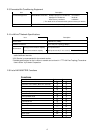
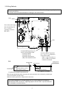
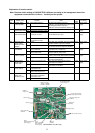
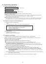
3-4 Electrical Wiring
Transformer
Switch Function selection
M-NET address switch
Tremination selection switch
(
LONWORKS
®
)
SYMBOL EXPLANATION
Power circuit boardP. B
L.B LM ADAPTER main board
F
SWU1, 2
Service switch (
LONWORKS
®
)SWL
Fuse AC250V 2A T
NAMESYMBOL
SW1, 2, 3
T1.2
SW71
LONWORKS
®
transmission line
Grounding terminal
M-NET transmission line
Power source
LED
TB21
Power Supply switch connectorCN40/CN41
TB2
TB1
Maintenance LED
Use LED001 as Wink
(
LONWORKS
®
) at SW2-1
˜
6 OFF
LED001
˜
004
Status LED
LED009/201/502/402
Service LED (LONWORKS
®
)LEDL
NAMESYMBOL
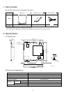
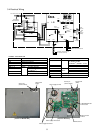
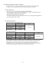
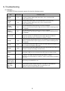
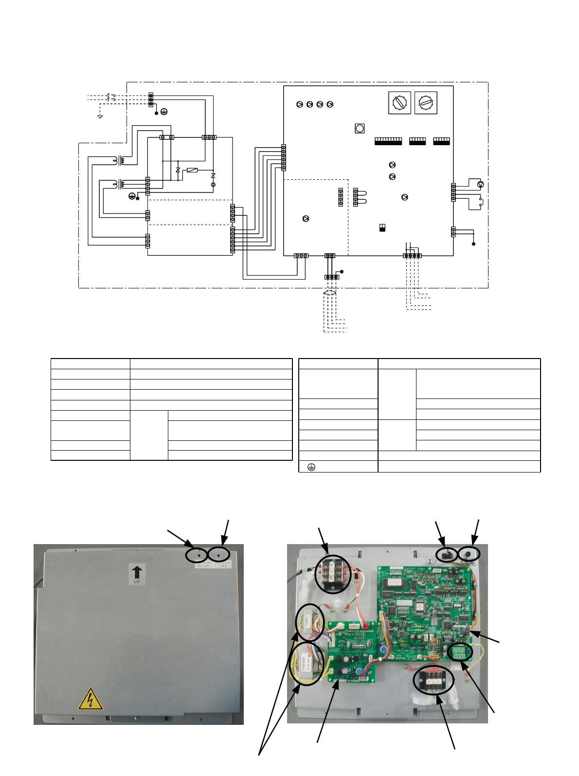
Terminal
block
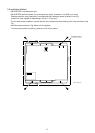
Service pin
(Service switch)
Service LED
(LEDL)
Power supply terminal
LM ADAPTER main
circuit board
LON connection
terminal
M-NET terminal
Power supply circuit board
Power supply transformer
[ Top Cover Removed ]
Service pin
(Service switch)
Service LED
(LEDL)
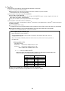
[ Exterior of LM ADAPTER ]