


MC USN Information
11
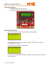
Once the USN has connected to the device it will display the following message:
This indicates that the USN board has successfully established connectivity with the device.
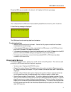
If the following message is displayed:
The USN board is not receiving data from the device.
Troubleshooting
• Recheck you connections to the board. Ensure that all proper connections have been
made based on the device type.
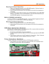
• In the case of a PCA type controller, ensure that the JP5 jumper on the M2C board is on
pins 2 and 3 (closest to the edge of the board).
• In the case of a swing panel, ensure that the slide switch on the MC-RS board is in the DCE
position and that the ICOM setting is configured for the correct COM port.
• If this job is a modification, ensure that the updated CGPC or PCA chips have been
installed into the controller.
Diagnostic Menus
To access diagnostic menus, place (only) the F8 switch in the UP position. This menu is used
primarily by MCE technicians for diagnostic purposes.
• Version screen: Displays the MC-USN version.
• iReport Connection Screen: This option shows information related to iReport connectiv-
ity. When connected, the iReport TCP port number, connection state, and IP address are
displayed.
• Number of Xport Resets: This option displays the number of Xport resets since the last
time the board was reset. Excessive resets may indicate a network-related issue.
• Device Communication Queue Health: This option displays the highest number of bytes
sent by the connected controller device that had to be stored before processing. It also dis-
plays the maximum number of bytes that can be stored. The final number is a real-time
display of the number of bytes buffered before processing. If current number of buffered
bytes is the same as the max then the device has sent data too quickly for the USN to pro-
cess. MCE use only.