


Chapter 2 l l Installation
8
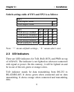
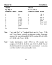
Switch settings table of SW1 and SW2 is as follows:
SW1
*Full-duplex mode Off
Half-duplex mode On
SW2 Pin1 Pin2 Pin3 Pin4
*TxD always enabled On Off X X
TxD always disabled Off Off X X
TxD enabled by RTS Off On X X
*RxD always enabled X X On Off
RxD enabled by /RTS X X Off On
Note: ‘ * ‘ means default settings , ‘ X ‘ means don’t care
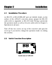
2.3 LED Indicators
There are LED indicators for TxD, RxD, RTS, and PWR on top
of A50/A51. The indicator is not lighted on when not connected
with signal or power. On the contrary, it will be lighted on and
be in one of the red, green or orange colors.
TxD indicator stands for data transmitting from RS-232 to
RS-422/RS-485. It shows green when connected and no data
transmitting. It shows orange when connected and transmitting
data.