


Chapter 3 l l Operation
18
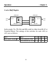
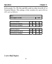
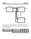
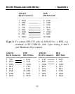
In the graph, TA, TB, RA and RB could be either from RJ-45 or
Terminal Block. The settings of the switches for each A50 (or
A51) are as follows:
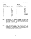
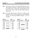
SW1 SW2 Pin1 Pin2 Pin3 Pin4
Full-duplex mode Off TxD always enabled On Off X X
RxD always enabled X X On Off
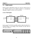
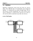
A50/A51
RA
RB RS-422/ RS-232
TB RS-485
TA
GND
DTE/
DCE
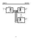
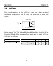
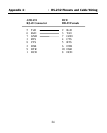
A50/A51
RS-232
TA
RS-422/ TB
RS-485 RB
RA
GND
DTE/
DCE
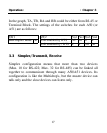
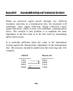
A50/A51
RA
RB RS-422/ RS-232
TB RS-485
TA
GND
DTE/
DCE