


PCI Express Board User’s Manual Hardware Installation
2-2
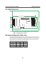
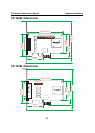
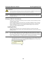
CP-118EL Dimensions
132 mm (5.20 in)
51.65 mm
(2.03 in)
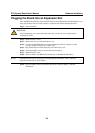
MU860
TX2
RX1 RX2
Tx3
Rx3
Tx4
Rx4
Tx5 Tx6
Rx5
Rx6
Tx7
Rx7
Tx8
Rx8
TX1
DIP
12345678
ON
DIP
12345678
ON
DIP
12345678
ON
S1
S2
S3
Mode
S1 S2 S3
RS-232
RS-422
ON
ON OFF
Mode
S1 S2 S3
4-WIRE
RS-485
2-WIRE
RS-485
OFF
OFF OFF
OFFON OFF
46.9 mm (1.85 in)
64.41 mm
(2.54 in)
59.91 mm
(2.36 in)
121 mm
(4.76 in)
NOTE: Use JP1/2/3/4/5/6/7/8 to activate the Termination Resistors for ports 1/2/3/4/5/6/7/8.
Open Termination Resistor is NOT active
Short Termination Resistor is ACTIVE
DIP Switch Settings (CP-118EL only)
CP-118EL has three onboard DIP Switch arrays, each with 8 switches, shown as follows and on
the board (see the above block diagram) as S1, S2, and S3. The switches are used to select one of
four serial interfaces—RS-232, RS-422, 4-wire RS-485, 2-wire RS-485—for each of the eight
ports. Note that S3 selects between RS-232 and RS-422/485, S2 selects between RS-422 and
RS-485, and S3 selects between 2-wire and 4-wire RS-485.
Mode S1 S2 S3
RS-232 --- --- ON
RS-422 --- ON OFF
4-Wire RS-485 ON OFF OFF
2-Wire RS-485 OFF OFF OFF