


2-17
Hardware Setup
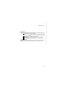
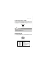
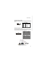
Parallel/Serial Port Bracket (Optional)
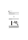
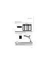
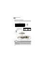
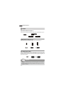
Parallel Port Connector: JLPT1
The mainboard provides a 26-pin header for connection to an optional parallel port
bracket. The parallel port is a standard printer port that supports Enhanced Parallel
Port (EPP) and Extended Capabilities Parallel Port (ECP) mode.
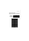
Pin Signal Name
Pin Signal Name
1 RSTB# 2 AFD#
3 PRND0 4 ERR#
5 PRND1 6 PINIT#
7 PRND2 8 LPT_SLIN#
9 PRND3 10 GND
11 PRND4 12 GND
13 PRND5 14 GND
15 PRND6 16 GND
17 PRND7 18 GND
19 ACK# 20 GND
21 BUSY 22 GND
23 PE 24 GND
25 SLCT 26 GND
2
1
26
25
JLPT1
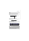
COM2
1
9
2 10
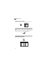
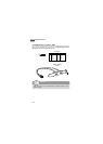
Serial Port Connector: COM 2
This connector is a 16550A high speed communications port that sends/receives 16
bytes FIFOs. You can attach a serial device to it through the optional serial port
bracket.
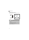
PIN SIGNAL DESCRIPTION
1 DCD Data Carry Detect
2 SIN Serial In or Receive Data
3 SOUT Serial Out or Transmit Data
4 DTR Data Terminal Ready
5 GND Ground
6 DSR Data Set Ready
7 RTS Request To Send
8 CTS Clear To Send
9 VCC_COM3 Power Source
Pin Definition