


Hardware Setup
2-19
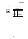
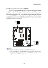
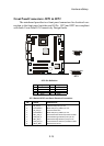
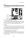
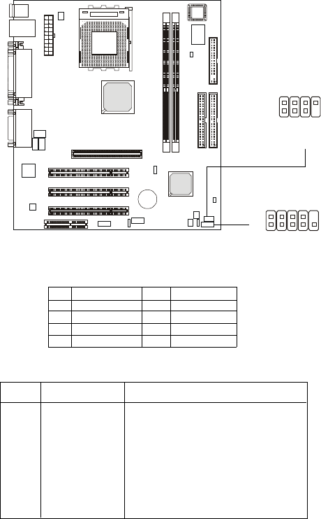
Front Panel Connectors: JFP1 & JFP2
The mainboard provides two front panel connectors for electrical con-
nection to the front panel switches and LEDs. JFP1 and JFP2 are compliant
with Intel
®
Front Panel I/O Connectivity Design Guide.
Pin Signal
1 GND
2 SPK-
3 SLED
4 BUZ+
Pin Signal
5 PLED
6 BUZ-
7NC
8 SPK+
JFP2 Pin Definition
PIN SIGNAL DESCRIPTION
1 HD_LED_P Hard disk LED pull-up to +5V
2 FP PWR/SLP MSG LED pull-up (330ohm) to +5V
3 HD_LED_N Hard disk active LED
4 FP PWR/SLP MSG LED pull-up (330ohm) to +5V
5 RST_SW_N Reset Switch low reference pull-down to GND
6 PWR_SW_P Power Switch high reference pull-up to +5V
7 RST_SW_P Reset Switch high reference pull-up to +5V
8 PWR_SW_N Power Switch low reference pull-down to GND
9 RSVD_DNU Reserved. Do not use.
JFP1 Switch/LED Front Panel Electrical Connection
1
8
JFP2
2
7
JFP1
1
9
10
2