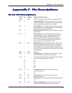
Appendix F - Pin Descriptions
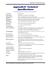
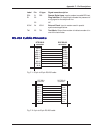
RDL 21 RDL Remote Digital Loop Input to modem to enable RDL test.
RI 22 Ring Indicator RI output high indicates the presence of
a ring signal on the telephone line.
23 NC
XCLK 24 XCLK External Clock Input to modem used in special
synchronous applications.
TM 25 TM Test Mode Output from modem to indicate modem is in
one of the test modes.
RR
RR
R
SS
SS
S
--
--
-
232 Cab232 Cab
232 Cab232 Cab
232 Cab
le Ple P
le Ple P
le P
inoutsinouts
inoutsinouts
inouts
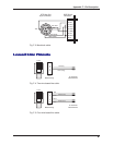
20 DTR
22 RI
8CD
7 GND
6 DSR
5 CTS
4 RTS
3RD
2TD
DTE DB-25
connector
DCE DB-25
connector
DTR 20
RI 22
CD 8
GND 7
DSR 6
CTS 5
RTS 4
RD 3
TD 2
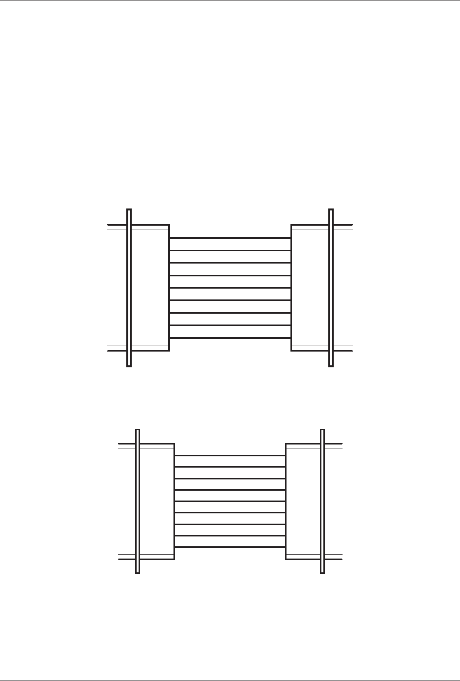
Fig. F-1. 25-pin to 25-pin RS-232 cable.
20 DTR
22 RI
8CD
7 GND
6 DSR
5 CTS
4 RTS
3RD
2TD
DCE DB-25
connector
DTE DB-9
connector
DTR 4
RI 9
CD 1
GND 5
DSR 6
CTS 8
RTS 7
RD 2
TD 3
Fig. F-2. 9-pin to 25-pin RS-232 cable.
Label Pin I/O type Signal name/description


