


44
MultiFRAD II User Guide
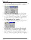
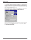
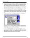
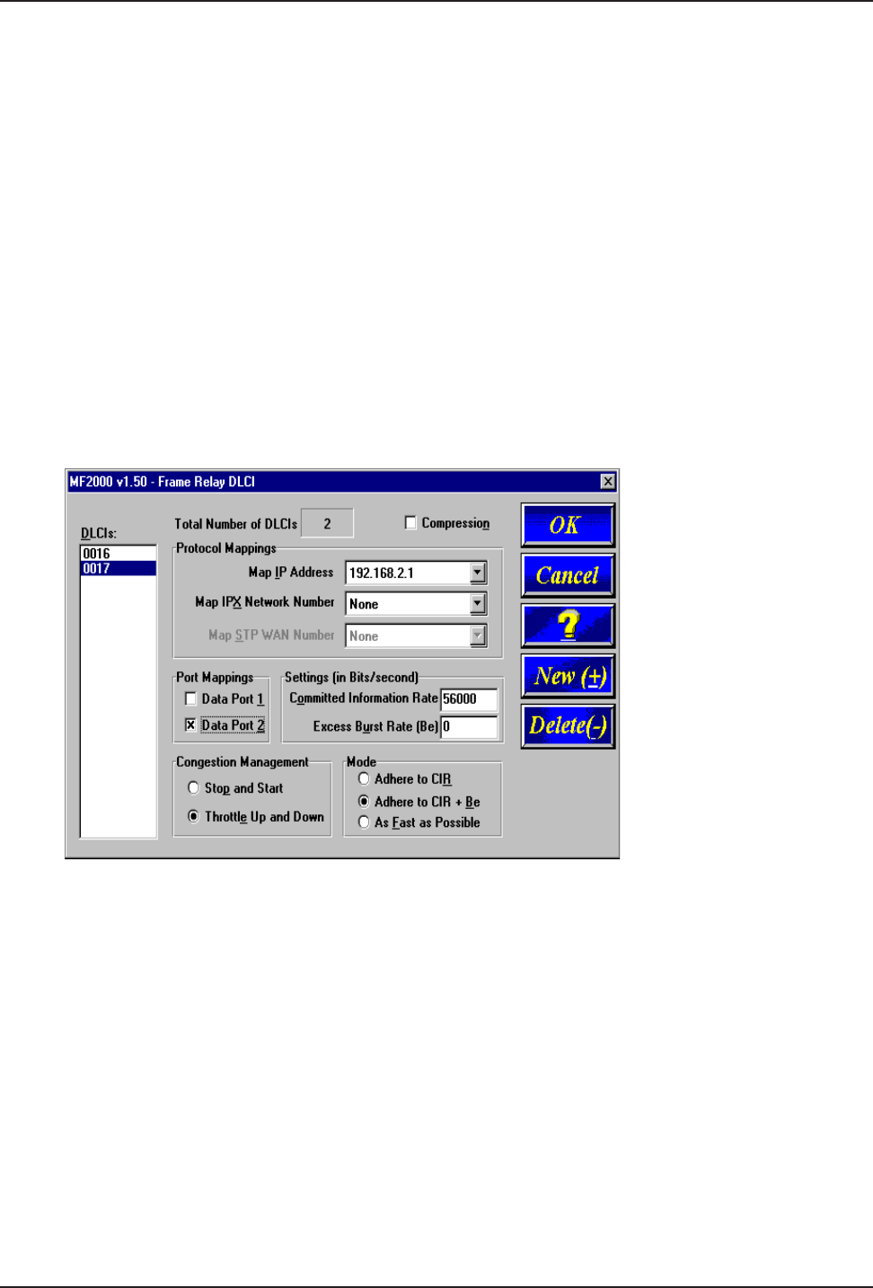
Congestion Management, Mode, and CIR/Be settings are used to avoid congestion and possible loss
of data. The Committed Information Rate (CIR) and Excess Burst rate (Be) settings are throughput
amounts determined by the network and user when each DLCI is ordered. The CIR is the basic
throughput which the network will try to set aside for that DLCI. It will always be equal to or less than
the actual access rate of the physical line (i.e., if the frame relay physical link is a 56K DDS line, the
sum of the CIRs of all DLCIs on that link should not exceed 56K bps). The Be is the excess burst
throughput rate (added to CIR) that the network should accept for that DLCI before significant loss of
data occurs due to the discarding of frames during times of congestion. Note, however, that in frame
relay there is no absolute guarantee of a congestion-free link, regardless of CIR and Be settings. The
CIR and Be settings on the MultiFRAD should match the settings that the network has provisioned.
The Congestion Management and Mode settings determine how the MultiFRAD handles congestion.
The Mode selects whether the MultiFRAD should use its own throughput calculations to avoid
congestion, or simply send data to the network as fast as possible. The MultiFRAD calculates
throughput after every CIR Measurement Interval, and can limit throughput to either the CIR (Adhere
to CIR) or the CIR plus the Be (Adhere to CIR+Be). The Congestion Management setting selects
whether the MultiFRAD should stop sending data when congestion is indicated (Stop and Start), or
gradually reduce throughput during times of congestion (Throttle Up and Down).
Compression can be enabled on a per-DLCI basis by clicking on the Others-Compression box. If
compression is required, it must be enabled on both the local and remote ends of the PVC.
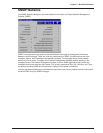
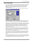
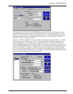
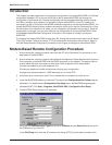
To map a new DLCI (e.g., 17) to a protocol, return to the MultiFRAD Setup menu and then click the
protocol stack that you are using. In the lower left part of the protocol stack dialog box a list of Logical
WANs is displayed. To add a new logical WAN, click the Add (+) button and the next logical WAN
number will appear in the list on the left hand side of the dialog box.
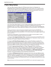
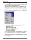
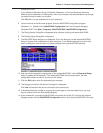
For example let’s map our new DLCI 17 to the IP protocol as a WAN 2 with an IP Port Address of
192.168.2.1, an IP Mask of 255.255.255.0, and a remote IP Address of 192.168.2.2. From the
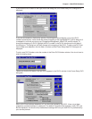
MultiFRAD Setup menu, click the IP button. The IP Setup dialog box is displayed. Click the WAN tab
at the top of the dialog box. The WAN parameters are displayed. Click the Add (+) button and WAN 2
is added to the List of Logical WANs. Default IP addresses will be displayed for the Port Address and
Remote Address and a default IP Mask will appear in its window. If either address or mask needs to
be changed, click the appropriate window and the change the numbers.