


15
Chapter 2 - Installation
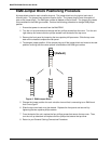
Valid Voice/Fax Channels
The following are the only valid Voice/Fax channels that can be made at this time:
• FXS to FXS • FXS to FXO
• FXS to E&M • E&M to E&M
For example, the FXS configuration at the local site can talk to an FXO configuration at the
remote site.
Cabling your MultiFRAD 3000
Cabling your MultiFRAD involves general cabling connections for all models, data channel
connections, and Voice/Fax connections for models connecting to telephone equipment. The
general cable connections involve connecting power, command port, composite link device, and
LAN connections. The data channel connections involve connecting data devices, such as
multiplexers, or other MultiFRAD 3000s if you are using the hub feature. The final cable
connections involve connecting your telephone equipment to the voice/fax channels. The
following procedure details the cable connections for each type of connection.
Note: Before starting your general cable connections, perform the E&M Jumper Block
Positioning Procedure if a voice/fax channel will be connected to an E&M trunk that is Type 1,3,4,
or 5 rather than the default position of Type 2.
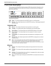
General Cable Connections
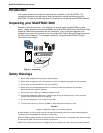
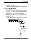
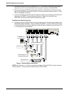
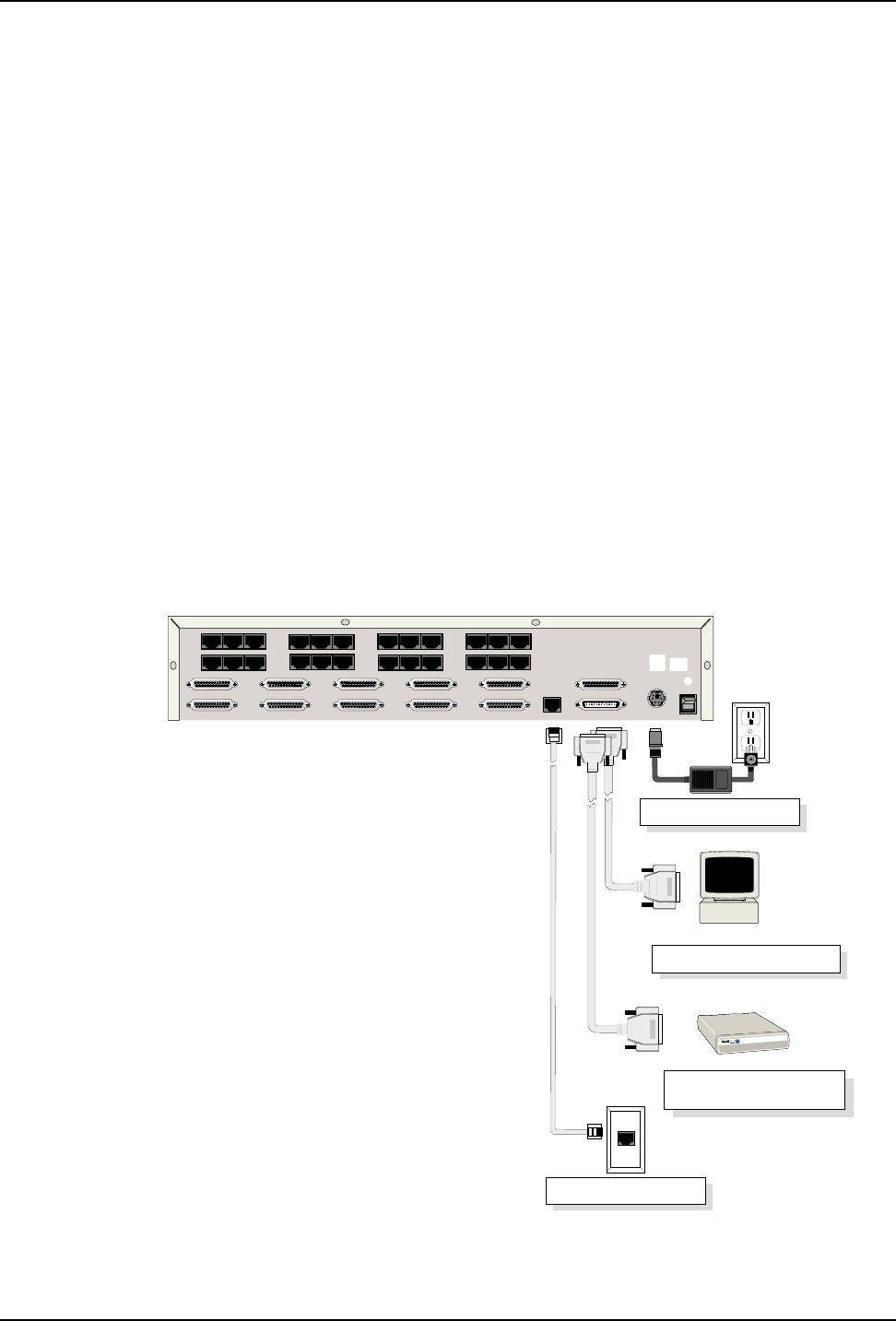
1 Connect one end of the power supply to a live AC outlet and connect the other end to the
MultiFRAD as shown in Figure 3. The power connector is a 7-pin circular DIN connector.
Ethernet Connection
Command Port Connection
T1 CSU/DSU or Comparable
Link Device
E&M FXO FXS E&M FXO FXS E&M FXO FXS E&M FXO FXS
VOICE/
FAX
CHANNEL
8
VOICE/
FAX
CHANNEL
4
VOICE/
FAX
CHANNEL
7
VOICE/
FAX
CHANNEL
3
VOICE/
FAX
CHANNEL
6
VOICE/
FAX
CHANNEL
2
VOICE/
FAX
CHANNEL
5
VOICE/
FAX
CHANNEL
1
CHANNEL 10
CHANNEL 9
CHANNEL 8
CHANNEL 7
CHANNEL 6
CHANNEL 5
CHANNEL 4
CHANNEL 3
CHANNEL 2 (RS232/V.35)
CHANNEL 1 (RS232/V.35)
10BASET
ETHERNET
COMMAND PORT
EXT. COMPOSITE LINK (RS232/V.35)
POWER
I
O
GND
T1 DSU
MONITOR
XMT RCV
INTERNAL
COMPOSITE
LINK
Power Connection
Figure 3. General Cable Connections