


Chapter 1 - Introduction and Description
MT3334SMI 13
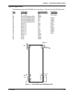
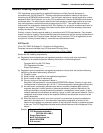
Typical Application
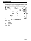
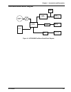
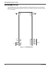
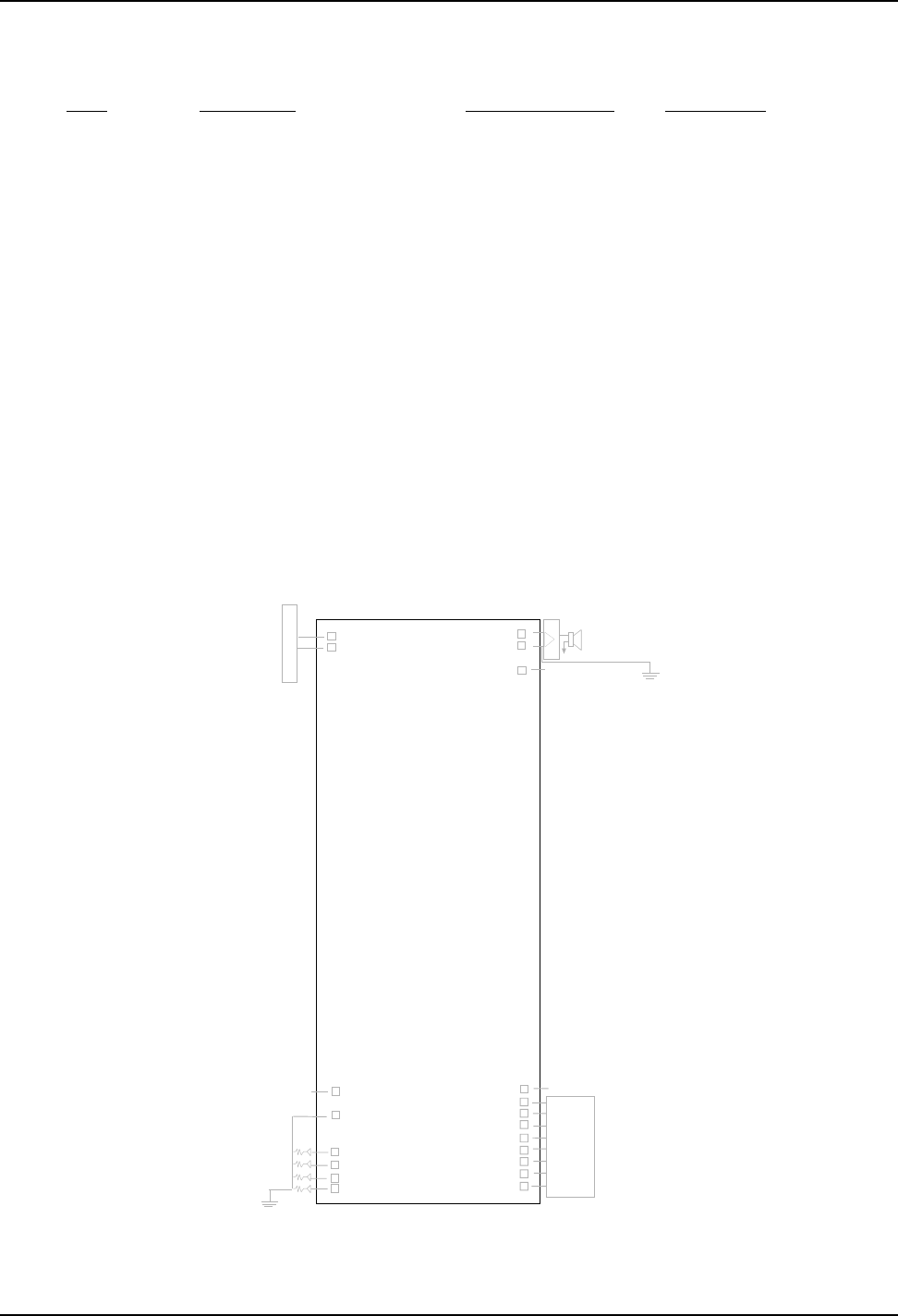
The table below shows the MT3334SMI pinouts and Figure 1-6 illustrates a typical OEM application.
Pin # Circuit Type Signal Description Input/Output
1RJ
-11 Jack Tip Input/Output
2 RJ-11 Jack Ring Input/Output
26 External Call Status LEDs DGND
29 External Call Status LEDs DCD Output
30 External Call Status LEDs RX Output
31 External Call Status LEDs DTR Output
32 External Call Status LEDs TX Output
33 Serial TTL RTS Input
34 Serial TTL RXD Output
35 Serial TTL TXD Input
36 Serial TTL RI Output
37 Serial TTL DSR Output
38 Serial TTL CTS Output
39 Serial TTL DCD Output
40 Serial TTL DTR Input
41 Serial TTL DGND
61 Power VCC
63 Audio AGND
64 Audio SPKR
24
26
29
30
31
32
1
2
1 - x
2 - x
3
4
5 - x
6 - x
64
63
61
Speaker Driver
Circuitry
+5v DC Power
RJ-11
Jack
41
40
39
38
37
36
35
34
33
Digital Ground
UART
Reset
Call-status
LED
Circuitry
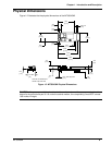
Figure 1-6. MT3334SMI Typical OEM Application