


9
Cabling
Cabling Procedure
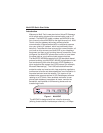
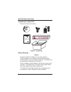
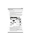
Cabling involves connecting the master MultiVOIP to your LAN
and telephone equipment.
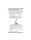
1. If you are connecting any Voice/Fax Channel to an E&M
trunk other than type 2, perform the E&M Jumper Block
Positioning procedure in the following section before
connecting power to the unit.
2. Connect one end of the power supply to a live AC outlet
and connect the other end to the MultiVOIP as shown in
Figure 3. The power connector is a 7-pin circular DIN
connector.
E&M FXO FXS E&M FXO FXS E&M FXO FXS
VOICE/
FAX
CHANNEL
8
VOICE/
FAX
CHANNEL
4
VOICE/
FAX
CHANNEL
7
VOICE/
FAX
CHANNEL
3
VOICE/
FAX
CHANNEL
6
VOICE/
FAX
CHANNEL
2
VOICE/
FAX
CHANNEL
5
VOICE/
FAX
CHANNEL
1
CHANNEL 10
CHANNEL 9
CHANNEL 8
CHANNEL 7
CHANNEL 6
CHANNEL 5
CHANNEL 4
CHANNEL 3
CHANNEL 2 (RS232/V.35)
CHANNEL 1 (RS232/V.35)
10BASET
ETHERNET
COMMAND PORT
EXT. COMPOSITE LINK (RS232/V.35)
POWER
I
O
GND
T1 DSU
MONITOR
XMT RCV
INTERNAL
COMPOSITE
LINK
E&M FXO FXS
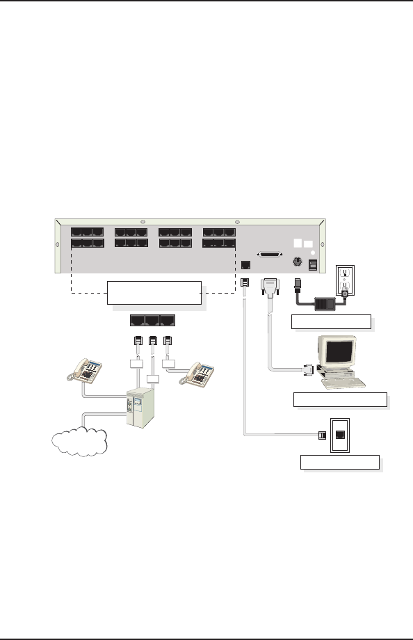
Ethernet Connection
Command Port Connection
Power Connection
FXS
FXO
E&M
FXSE&M
FXO
PSTN
Voice/Fax Channel 1 - 8
Connections
Figure 3. Cable Connections
3. Connect the MultiVOIP to a PC by using a DB-9 to DB-25
cable. Plug the DB-25 end of the cable into the
Command port of the MultiVOIP and the other end into
the serial port on the PC. See Figure 3.
4. Connect a network cable to the ETHERNET 10BASET
connector on the back of the MultiVOIP. Connect the other
end of the cable to your network.