


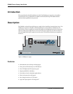


PS9600 Power Supply User Guide
10 CommPlete Communications Server
Introduction
This chapter provides information needed to identify and fix problems with the PS9600 power supply
module. Problems can be observed on the CommPlete system’s front panel LEDs, the control PC’s screen,
or via audio alarm or alarm report. In addition, problems can be found when performing the Diagnostic
Tests documented elsewhere in the CommPlete Communications Server
User Guide
.
LED Indicators
The CommPlete Communication Server’s front panels contains the following indicators.
• MR9600 controller LEDs.
• Modem card LEDs. The number of LEDs on your modem card may vary, depending on the type of
modem card in your chassis. Please refer to your modem’s user guide for LED descriptions.
• PS9600 power supply LED.
The PS9600 power supply LED is described below. Each of the other LED indicators is described in the
applicable manual.
Power Supply LED
This LED goes out if one of the PS9600 power supply outputs goes low or fails altogether. In normal
operation it is lit. The recovery procedure to be used depends on whether the CommPlete chassis has one
or two PS9600 power supplies installed.
Indication: LED is on (either one or two PS9600s installed).
Meaning: The power supply (or supplies) are operating properly.
Recovery: No action required.
Indication: LED is off (one PS9600 installed).
Meaning: At least one of the outputs is low or out.
Recovery: Turn off the power supply, remove it, and check the fuse. Replace the fuse if it is blown;
call Technical Support if the fuse is good (Chapter 5).
Indication: LED is off (two PS9600s are installed).
Meaning: At least one of the outputs is low or out. Power is being supplied by the second PS9600.
Recovery: Turn off the PS9600 that has the LED off, and remove the PS9600. Replace the fuse if it is
blown; call Technical Support if the fuse is good (Chapter 5).
Adjustment of the PS9600 Power Supply
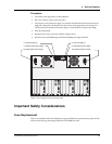
For optimal operation of the CommPlete Communications Server, the 5 V output of the PS9600 power
supply should be adjusted to 5.1 VDC. The 5-volt test points are located on the back of the chassis between
the power supply fans.