


SPL-92106N page 3 of 4
Precautions
Cutting or sharp bending the capillary will cause permanent damage
to the SWICHGAGE
®
and will void the warranty. Excess capillary
should be carefully coiled and secured away from damage. Do not
route capillary along exhaust manifold. Avoid routing capillary at a
level higher than gage mounting.
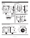
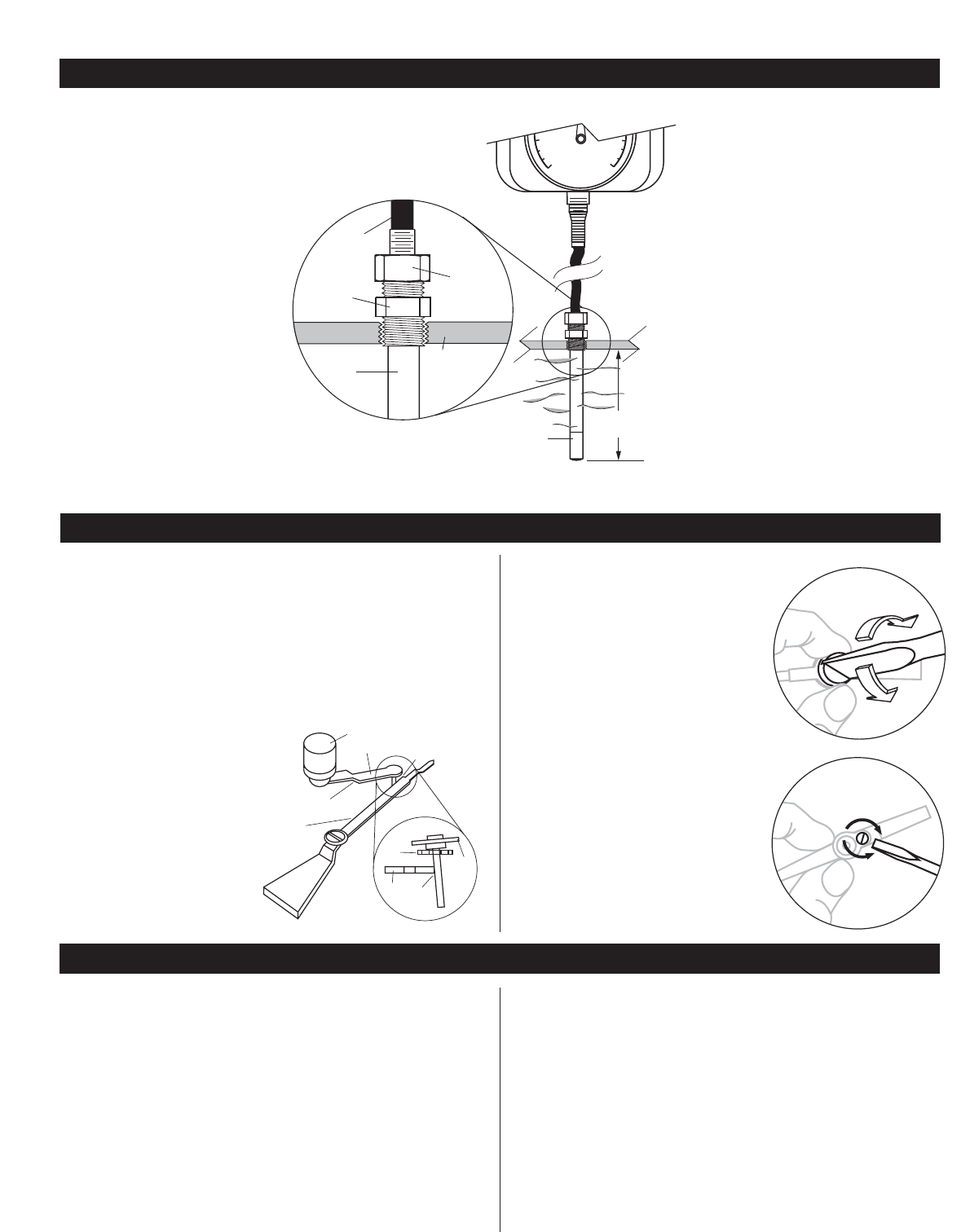
Installing Sensing Bulb
1. Install the
1
/2 NPT adapter into the
application.
2. Slip compression nut and ferrule
onto bulb.
3. Insert the sensing bulb directly
through the adapter and fully
immerse it into the process without
interference. Be sure to leave enough of
the bulb to allow the compression nut and
ferrule to be tightened.
4. Keep the bulbs active section in the middle of the process flow.
5. Tighten the compression nut and ferrule. This will keep the
bulb in place and obtain a full seal.
100
0
500
800
6 in.
(152 mm)
transmitting
tube or
capillary
Sensing
bulb
insertion
compression
nut
active
section of
sensing bulb
Wall
SWICHGAGE
®
Adapter
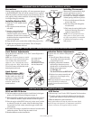
Limit Contact Adjustments
Facing the dial, left side knob is “Low limit” contact. Right side is
“High limit” contact.
NOTE: the 45TE Series features a stacked
limit indicator knob with both limit adjust-
ments included. The bottom half knob
adjusts the “Low” limit indicator, the top
half is to adjust the “High” limit indicator.
To set limit contact, turn the knob to the
desired point on the scale.
Limit Contact
Wiping Feature (SPL)
The force of pointer causes the
flexible contact arm (A) to “tilt”
resulting in a wiping action (D).
This clears away film or
corrosion formed on the
contact surfaces
.
Indication Pointer Adjustments
To reset to zero or to a known value proceed
as follows:
1. Turn off power. Remove the snap
ring and the lens/contact assembly
(or open hinged cover).
2. Hold the pointer hub with thumb
and forefinger then turn screw to
desired point. Avoid touching the gold
flashed, silver contact areas.
See DETAIL “A”.
For the 45TE Series see DETAIL“B”.
3. Replace lens contact assembly and
snap ring (or close hinged cover),
and turn on power.
NOTE: Span adjustments and recalibration
must be performed by an authorized
mechanic or return the unit to Frank W.
Murphy Mfr
.
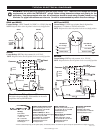
SPLC and SPLFC Series
1. Perform operation test after the unit is installed and wired appro-
priately (see Typical Electrical Diagrams on page 4).
2. When temperature is applied to the sensing bulb the pointer will trav-
el in a clockwise direction. (Adjust contacts to desired set points.)
3. Place the toggle switch (SPLC Series only) in the “start”position
or otherwise override low contact. After the indication pointer
rises past the low limit contact, return the toggle switch to the
“run”position.
4. To test the limit contacts, turn the limit contact to be tested until it
touches the pointer. That will trip the control circuit.
5. Reset the shutdown or alarm circuit device.
45TE Series
1. Perform steps 1 and 2 in the SPLC Operation Test Instructions.
2. To test the switches, turn the limit indicator until it touches the
pointer, then continue to rotate until the snap-switch operates*.
3. Reset the shutdown or alarm circuit device.
*
The trip point indicator will stop the pointer movement slightly
before the snap-switch operates. As temperature continues to
increase or decrease, the trip point setting is reached
.
SENSING BULB-THERMOWELL INSTALLATION
LIMIT CONTACTS / INDICATION POINTER ADJUSTMENTS
OPERATION TEST INSTRUCTIONS
E
A
B
C
D
B
A
D
C
A. Contact arm-flex
B. Contact arm
C. Pointer Contact
D. Initial point of contact
E. Limit contact knob
Turn to lower
pointer
Turn to raise
pointer
DETAIL “A”
Turn to
lower pointer
DETAIL “B”
Turn to raise
pointer
Installing Thermowell
Thermowell is recommended for high
pressure applications or corrosive
environments. It also allows tempera-
ture sensor to be changed or adjusted
without opening connection to process.
1. First screw the thermowell into the
process (pipe line).
2. Pass the sensing bulb through the
nut and ferrule.
3. Fully insert the sensing bulb into the
thermowell housing and secure it
with the compression nut.
NOTE: The use of temperature trans-
mitter grease or silicon grease on the
tip of the sensing bulb is recommended
to facilitate heat transfer to sensing
bulb junction.