


Bulletin AT-95026B page 2 of 4
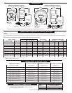
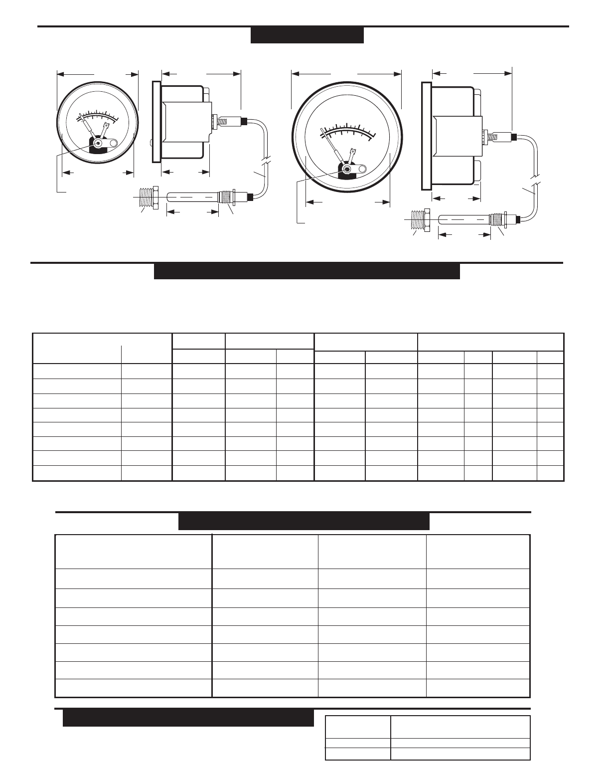
2-1/4 in.
(57 mm)
2-1/2 in.
(64 mm)
2-29/32 in.
(74 mm)
2-1/2 in.
(64 mm)
1-11/32 in.
(34 mm)
2-11/16 in. (68 mm)
Mounting hole dia.
1-27/64 in.
(36 mm)
2-1/16 in. (53 mm)
Mounting hole dia.
Mounting
Clamp
Mounting
Clamp
°C
TEMPERATURE
1-1/2 in.
(38 mm)
1/2 NPT
M
U
R
P
H
Y
S
W
I
C
H
G
A
G
E
®
Contact
Adjustment
1/16 in. hex
°C
TEMPERATURE
130
160
210
250
80
100
60
230
120
M
U
R
P
H
Y
S
W
I
C
H
G
A
G
E
®
°F
Contact
Adjustment
1/16 in. hex
Adapter Nut
†
Union Nut
Sensing Bulb
†
Union Nut
130
160
210
250
80
100
60
230
120
°F
1-1/2 in.
(38 mm)
1/2 NPT 5/8-18 U.N.F.
Adapter Nut
†
Sensing Bulb
†
5/8-18 U.N.F.
4 ft. (1.2 m)
long
Capillary
†
4 ft. (1.2 m)
long
Capillary
†
†
Standard combinations. See Murphy bulletin T-8428B for optional sensing bulb, engine adaptors and capillary combinations.
Dimensions
A20 Series Models (typical) A25 Series Models (typical)
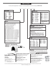
Ranges Available
Dual Scale Dial Single Scale
°Fahrenheit (°Celsius) °Celsius only
Std. Settings*
°F (°C) °C only
Max. Temp.
°F (°C)
20TABS and 25TABS Settings
Alarm** Shutdown
°F (°C) °C only °F (°C) °C only
Hi/Lo Settings
Low High
°F (°C) °F (°C)
32 – 160 (0 – 71) 0 – 70 215 (102) 150 (66) 66 32 (0) 150 (66) 140 (60) 60 150 (66) 66
32 – 120 (0 – 49) –– 185 (85) 110 (43) –– 32 (0) 110 (43) 100 (38) –– 110 (43) ––
130 – 220 (54 – 104) 45 – 100 260 (127) 210 (99) 85 160 (71) 210 (99) 200 (93) 80 210 (99) 85
130 – 250 (54 – 121) 50 – 120 310 (154) 210 (99) 97 160 (71) 210 (99) 200 (93) 95 210 (99) 100
160 – 320 (71 – 160) 70 – 160 370 (192) 300 (149) 150 200 (93) 300 (149) 290 (143) 145 300 (149) 150
140 – 300 (60 – 149) 60 – 140 340 (173) 275 (135) 130 200 (93) 275 (135) 265 (129) 125 275 (135) 130
180 – 350 (82 – 177) –– 400 (209) 330 (166) –– 240 (116) 330 (166) 320 (160) –– 330 (166) ––
300 – 440 (149 – 227) –– 500 (260) 400 (204) –– 300 (149) 400 (204) 390 (199) –– 400 (204) ––
* Standard setting for A20T, A25T, A20TE and A25TE models.
** SPDT snap-switch is the alarm switch.
NOTES
1. Values in ( ) are mathematical conversions from °F to °C–they do not reflect actual second scale range. U.S.A. standard scale is °F/°C.
2. For models A20TE and A25TE; the switch trip point cannot be set at either the low or high extreme of the scale. The trip point must allow for the reset differen-
tial.
3. For adjustable switch models, the trip point is adjustable only over the upper half of the scale.
Temperature Ranges and Factory Settings
Temperature Accuracy Chart
32 to 120°F (0 to 49°C) ± 12°F (± 6°C) ± 5°F (± 2.4°C) ± 6°F (± 3°C)
32 to 160°F (0 to 71°C) ± 20°F (± 10°C) ± 8°F (± 4.4°C) ± 7°F (± 4°C)
130 to 220°F (54 to 104°C) ± 6°F (± 3°C) ± 3°F (± 1.6°C) ± 4°F (± 2°C)
130 to 250°F (54 to 121°C) ± 9°F (± 5°C) ± 5°F (± 2.4°C) ± 4°F (± 2°C)
Temperature Range Lower
1
/3 of Scale Middle
1
/3 of Scale Upper
1
/3 of Scale
140 to 300°F (60 to 149°C) ± 10°F (± 5.2°C) ± 6°F (± 3°C) ± 5°F (± 2.4°C)
160 to 320°F (71 to 160°C) ± 10°F (± 5.2°C) ± 5°F (± 2.4°C) ± 5°F (± 2.4°C)
180 to 350°F (82 to 177°C) ± 12°F (± 6°C) ± 5°F (± 2.4°C) ± 5°F (± 2.4°C)
300 to 440°F (149 to 227°C) ± 9°F (± 5°C) ± 5°F (± 2.4°C) ± 4°F (± 2°C)
RANGE MAXIMUM PROCESS TEMPERATURE
≤250° (120°) 120% OF FULL SCALE
300° (140°) 350° (198°)
≥320° (160°) 120% OF FULL SCALE
MAXIMUM AMBIENT TEMPERATURE: -40° (-40°) thru 150° (66°)
Maximum Temperature