


Installation 00-02-0268 page 2 of 2
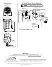
2-1/4 in.
(57 mm)
1-15/16 in. (49 mm)
1-15/16 in.
(49 mm)
2-1/2 in. (64 mm) min.
Clearance for Adjustment / Wiring
3/4 in. (19 mm) maximum
Panel Thickness.
2-1/16 in. (52 mm)
Mounting hole diameter.
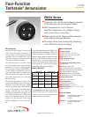
LED Indicators
Plug-in Wire
Connector
Push-on Plug and Wire Leads
18 AWG x 8 in. (1.0 mm
2
x 203 mm) long.
Mounting Clamp shown
assembled for thick panels
+
–
Dimensions
Front View
Side View
Back View
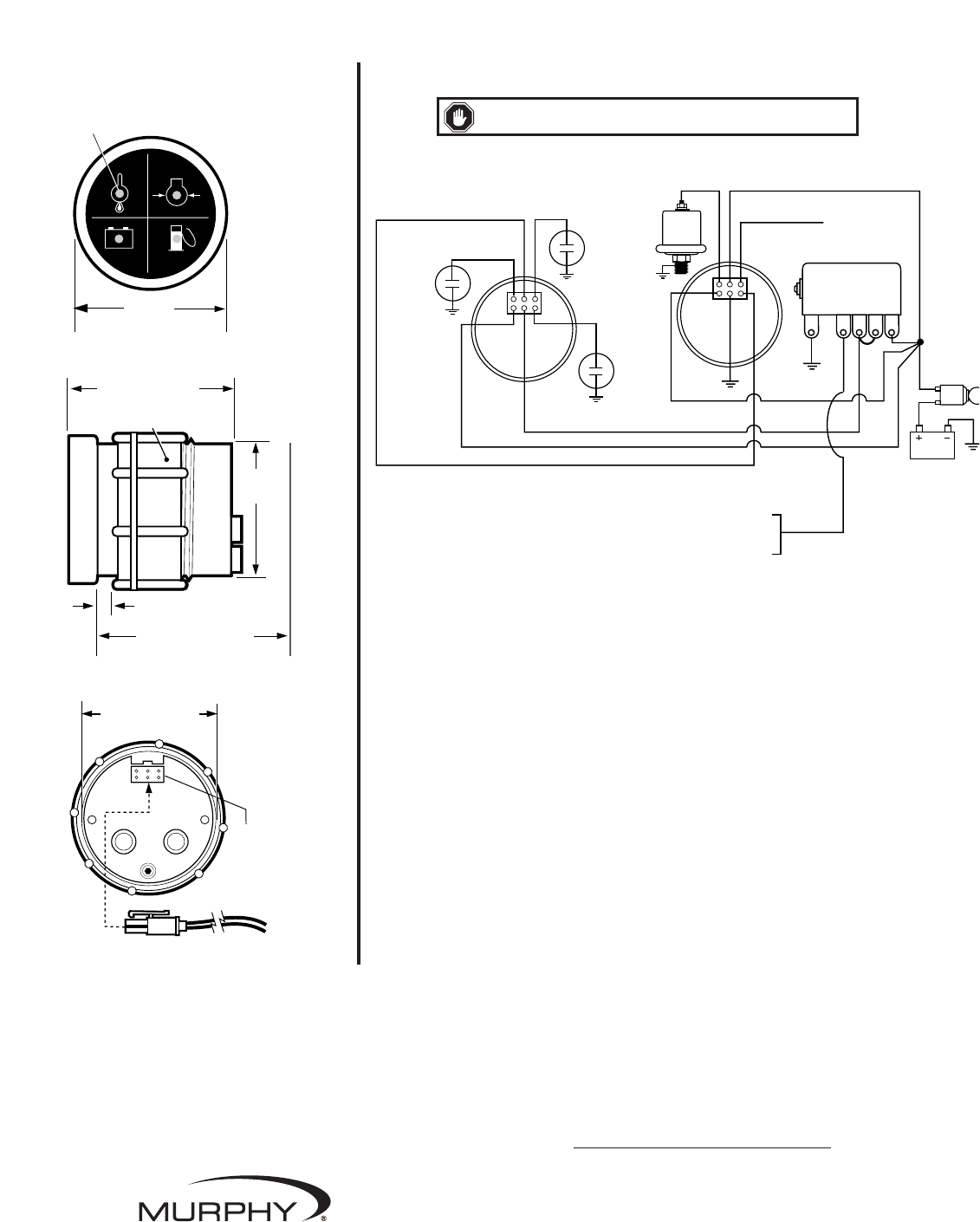
Battery
ON/OFF
Switch
Red
Blue
Brown
Orange
Black
518PH
Magnetic Switch
G NC SW1 SW2 B
Red
High
Temp.
Switch
Orange Oil Pressure
Brown
Battery
Input
Yellow / Dash
Light Circuit
Black
ESP-100
Sender
Yellow
Blue Fuel or
Glow Plug Input
Fuel or
Glow Plug
Switch
Battery
Switch
Close to illuminate
loss of battery voltage
Energized to run
components such as:
Ignition Coil
Fuel Valve
Rack Pull Solenoid
Note: Use of the black wire on the EN204-S and the 518PH Magnetic Switch (as shown in the diagram)
is required for engine shutdown.
For LED annunciation only, back wire is not used.
EN204-S Typical Wiring Diagram
WWAARRNNIINNGG
: Turn the power source OFF before wiring.
EN204-S
EGS21P-100
Warranty
A limited warranty on materials and workmanship is given with this FW Murphy product.
A copy of the warranty may be viewed or printed by going to www.fwmurphy.com/support/warranty.htm
In order to consistently bring you the highest quality, full featured products, we reserve the right to change our specifications and designs at any time.
In order to consistently bring you the highest quality, full featured products, we reserve the right to change our
specifications and designs at any time. MURPHY, the Murphy logo, and Tattletale
®
are registered and/or common
law trademarks of Murphy Industries, Inc. This document, including textual matter and illustrations, is copyright
protected by Murphy Industries, Inc., with all rights reserved. (c) 2006 Murphy Industries, Inc.
www.fwmurphy.com
918.317.4100 Email: sales@fwmurphy.com