EG21 and EGS21 Series Electric Gage and
SWICHGAGE
®
Installation
For Pressure, Temperature, Fuel Level, Voltmeter and Ammeter
EG21-96048N
Revised 05-05
Section 70
(00-02-0251)
Patents 5121109, 4975687 and 5608386
CAUTION
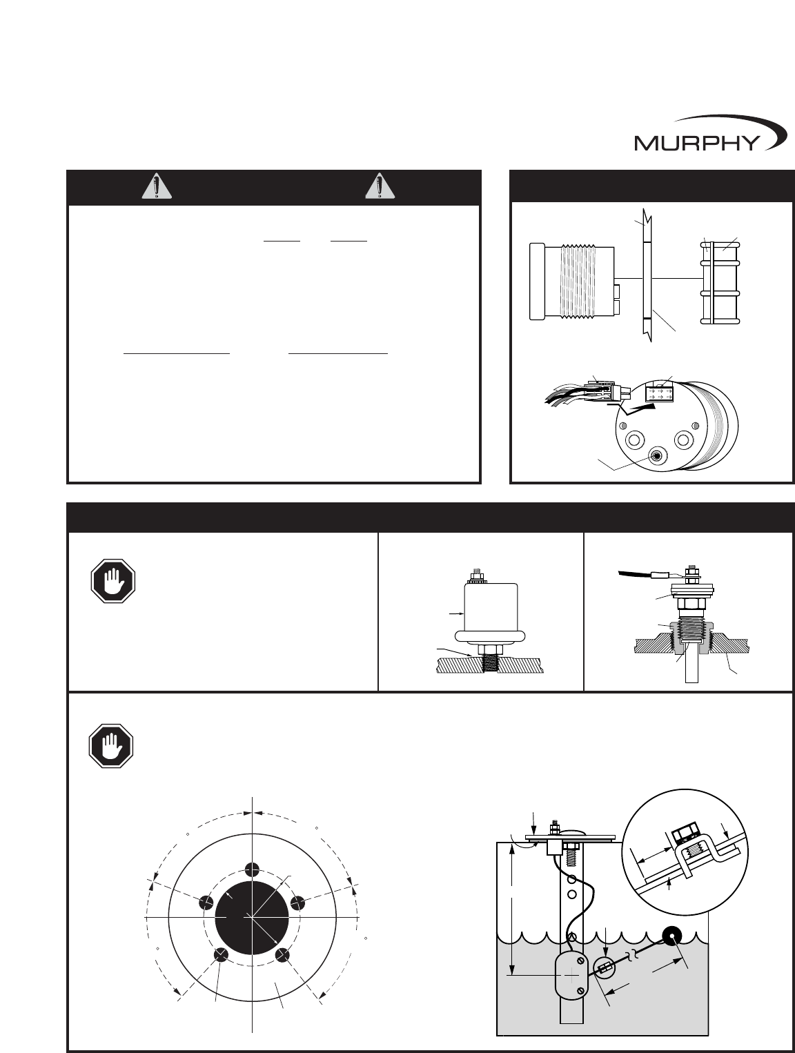
Panel
3/4 in. (19 mm)
maximum thickness
Mounting Clamp (Reversible)
Mounting Hole
2-1/16 in. (52 mm) Diameter
For Thick
Panels
For Thin
Panels
Plug-in
Connector
Push-on Plug
and Wire Leads
Set Point Adjustment
(SWICHGAGE
®
only)
Gage Installation
Sender
Adapter
Engine
Block
Copper
Washer
Sender
(Typical)
Engine block
pressure port
Pressure Sender
Temperature Sender
Fuel Level Sender
CAUTION: Extreme caution must be used in handling or working on or around the fuel tank. It must be worked on only in a
WELL VENTILATED area. Keep all flame and hot materials away from it. Do not smoke while working on or around the tank.
Avoid sliding or dragging the tank, or other actions which may cause a spark.
CAUTION: Do not use sender body to tighten.
If sealant tape or pipe dope is used on the
pressure sender, be sure that the tape or dope
does not plug the sender’s orifice.
Tank Installation
Shaft
Float Arm
Connector
See View A
Float
Arm
1/4 in.
(6 mm)
Float
Arm
Float Arm
Connector
View A
Gasket
Mounting Plate
(see Mounting Hole Dimensions)
Shaft
Arm
5/32 in.
(4 mm) dia.
5 Holes
1-3/4 in.
(44 mm)
dia.
68.5
1-1/16 in.
(27 mm)
radius
72
Mounting Plate
2-3/4 in. (70 mm)
diameter
72
68.5
Mounting Hole Dimensions
Sender Installation
IMPORTANT NOTICE FOR ALL EG21 ELECTRIC GAGES AND EGS21
ELECTRIC SWICHGAGE
®
S FOR 24VDC
AND 32VDC APPLICATIONS
A change in the dial illumination circuit has made it necessary to change the external wiring harness.
If you use the incorrect wiring harness, irreparable damage will occur to the gage mechanism.
The table below lists correct wire harness assemblies for units by manufacturing date. For
date code R1 (January 1996) or earlier (Q12, Q11, etc.) the wire harness can be identified
by P/N and by BLACK shrink tubing on the YELLOW wire. For date code R2 (February 1996)
and later (R3, R4, etc.) the wire harness can be identified by P/N and by RED shrink tubing
on the YELLOW wire.
Date Code R1 or Earlier Date Code R2 or Later
05004546 05006166
05004547 05006167
05004548 05006168
05004549 05006169
05004550 05006170
05004551 05006171
05004552 05006172
If dial illumination is NOT required, either wire harness can be used on any date code, if the
YELLOW wire is NOT connected.
EG21-96048N page 1 of 2


