


HD-96044N page 3 of 4
CAUTION: PERFORM THE WIRING OPERATION WITH THE POWER SOURCE “OFF”
MAGNETIC PICKUP INSTALLATION
A magnetic pickup is an AC generator. It is normally installed
into the flywheel housing of an internal combustion engine, so
that the starter ring gear acts upon it to generate a voltage pulse
each time a gear tooth passes the end of the sensor.
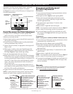
Magnetic Pickup Installation (see Figure 5)
Drill and tap a hole in the flywheel housing (See Specifications
Chart below for model and thread size). IMPORTANT: Drilling
too deep may damage ring gear teeth. Blow chips with air hose
when drilling and tapping hole.
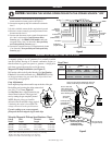
Gap Adjustment
Insert magnetic pickup and turn until it stops at the face of the gear.
Back-off the gear by turning the pickup counterclock-
wise
1/4, 1/2, or 3/4 turn (Figure 4)
.
See Gap Chart (above, right) to determine gap
distance based on the turn. Check gap clear-
ance by rotating the gear completely around.
NOTE: Magnetic pickup gap should be
adjusted so that the minimum voltage required
is attained at the engine’s lowest RPM. The
voltage will increase as the speed increases.
If erratic readings occur, remove magnetic
pickup and check the magnetic tip for metal chips.
Murphy Magnetic Pickup Specifications Chart
Pickup Total Threaded Thread
Model Length Length Size
MP3298* 3 in. (76 mm) 3 in. (76 mm) 5/8-18 UNF
MP7906
†
3 in. (76 mm) 3 in. (76 mm) 3/4-16 UNF
MP7905
††
4-1/2 in. (114 mm) 4-1/2 in. (114 mm) 3/4-16 UNF
*
Replaces 20-01-0080 and MP100. Lead wire hookup (12 in. [305 mm]).
†
Replaces 20-01-0081. Lead wire hookup (12 in. [305 mm]).
††
Replaces 20-01-0082. Lead wire hookup (12 in. [305 mm]).
Gap Chart
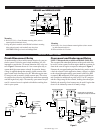
1. Connect terminal 5 on the HD9063 to engine ground and
connect terminal 4 to battery positive (see Figure 3).
2. Connect the magnetic pickup cable conductors to terminals
6 and 7.
3. If cable is shielded, connect shield to engine chassis ground.
4. If desired, connect a normally open test push button switch
between terminals 8 and 9.
5. Connect crank disconnect circuit to crank disconnect termi-
nals 1 thru 3 as discussed in Crank Disconnect Relay
Function, page 2. On HD9063-USOS models connect the
overspeed circuits 1 thru 3 as discussed in Overspeed Relay
and Underspeed Relay Function, page 2.
6. Connect the overspeed circuits to overspeed terminals 10 thru
12 as discussed in Overspeed Relay and Underspeed Relay
Function, page 2.
WIRING
123456789101112
(+) (+)( ) ( )
K1 K2
12
Common Common
Normally Open Normally Open
Normally Closed Normally Closed
Test
Pushbutton
DC Positive
DC Negative
(Engine Ground)
From Magnetic Pickup
To Engine
Crank Control
Circuit
or
to Shutdown
Circuits
(HD9063-USOS)
To
Shutdown
Circuits
THREAD
SIZE
5/8-18 UNF
3/4-16 UNF
1/4
1/2
3/4 1
GAP
.013 in. .028 in. .035 in. .055 in.
(0.33 mm) (0.71 mm) (0.88 mm) (1.39 mm)
.015 in. .030 in. .045 in. .062 in.
(0.38 mm) (0.76 mm) (1.14 mm) (1.57 mm)
TURN
1/4
1/2 3/4
AC
Meter
After adjusting,
set locknut.
Drill and tap casing
(see thread sizes in
Specifications).
Casing
Gear (must be made
of magnetic material).
NOTE: Clean gear casing
and magnetic sensor
of metal chips or filings.
Gap
(see Gap Chart)
Always use a two-conductor shielded cable. Ground the
shield to a metal frame ground at the engine end only.
Never run these wires
next to spark plug wires
or in wire loom with other
wires carrying inductive
loads or alternating current.
Figure 3
Figure 4
Figure 5