L-5937B page 2 of 2
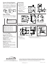
Typical Wiring Diagram
How to Order
Specify base model designator and options in
sequence shown below. Example: L100-HL.
Specify part number when ordering Repair Parts
or Kit. Example: 15000181
Repair Kit L100 and L100W:
15000103: Consists of glass, gasket,
4 screws, contact assembly, and float assembly.
Repair Parts L120 :
15010186: Contact screw assembly.
15010234: Float assembly.
Repair Kits L127 and L128:
15000180: Includes case, contact, 4 mounting
bolts, and 2 gaskets.
15000181 (L127 only): Includes 4 mounting
bolts, 2 gaskets, float assembly, ground strip,
wire, and mounting plate.
15000188 (L128 only): L128 less case assembly.
Dimensions
L100 and L100W
L120
L127 and L128
C
L
27/32 in.
(21 mm)
3-1/8 in.
(79 mm)
2-1/8 in.
(54 mm)
2-1/8 in.
(54 mm)
4-5/16 in.
(110 mm)
3-3/8 in.
(86 mm)
2-7/32 in.
(56 mm)
Mounting Holes 4 places,
5/16 in. (8 mm) diameter
2-7/32 in.
(56 mm)
2-3/4 in.
(70 mm)
2 in.
* *
(51 mm)
2-1/2 in.*
(64 mm)
2-15/64 in.
(57 mm)
Mounting
**
holes 4 places
5/16 in. (8 mm)
diameter
2-15/64 in.
(57 mm)
** Applies to L127 only
* Applies to L128 only
47/64 in.
(19 mm)
3/8 in.
(10 mm)
17/32 in.
(13 mm)
1-17/32 in.
(39 mm)
Mounting
holes 2 places
5/16 in. (8 mm)
Oil inlet
holes
L128 Mounting Dimensions
Base Model (refer to “Application” section)
L100: Sight gage with low limit switch.
L100W: Same as L100 except fittings.
L120: Sight gage with low limit switch.
L127: Sight gage with low limit switch.
L128: Sight gage with low limit switch.
____ - ____
Shipping Weight:
•
L127: 8 oz (0.23 kg)
•
L128: 10 oz (0.36 kg)
Shipping Dimensions (L127 and L128):
4-
3
/4 x 4-
3
/4 x 3-
1
/4 in. (121 x 121 x 83 mm)
Shipping Weight: 1 lb 8 oz (0.68 kg) Shipping Dimensions: 4-
3
/4 x 4-
3
/4 x 3-
1
/4 in. (121 x 121 x 83 mm)
Shipping Dimensions:
•
L100: 5-
1
/4 x 5-
1
/4 x 5-
1
/2 in.
(133 x 133 x 140 mm)
•
L100W: 4-
3
/4 x 4-
3
/4 x 3-
1
/4 in.
(121 x 121 x 83 mm)
Shipping Weight:
•
L100: 2 lbs. (0.91 kg)
•
L100W: 2 lbs. (0.91 kg)
Magneto
Murphy
magnetic
switch
Float
OR
Option
Blank: Low contact.
LF: Less fittings and hardware.
Printed in U.S.A. 06 8 789
Below is a typical wiring diagram for a level
Swichgage instrument. A Swichgage instru-
ment can be connected to a Murphy magnetic
switch or magneto. Switch Contact Rating is
2 A @ 30 VAC/DC resistive.
In order to consistently bring you the highest quality, full featured products, we reserve the right to change our
specifications and designs at any time. MURPHY, the Murphy logo, and Swichgage
®
are registered and/or common
law trademarks of Murphy Industries, Inc. This document, including textual matter and illustrations, is copyright
protected by Murphy Industries, Inc., with all rights reserved. (c) 2006 Murphy Industries, Inc.
www.fwmurphy.com
918.317.4100 Email: sales@fwmurphy.com


