


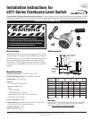
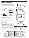
L-94071N page 2 of 2
INSTALLATION
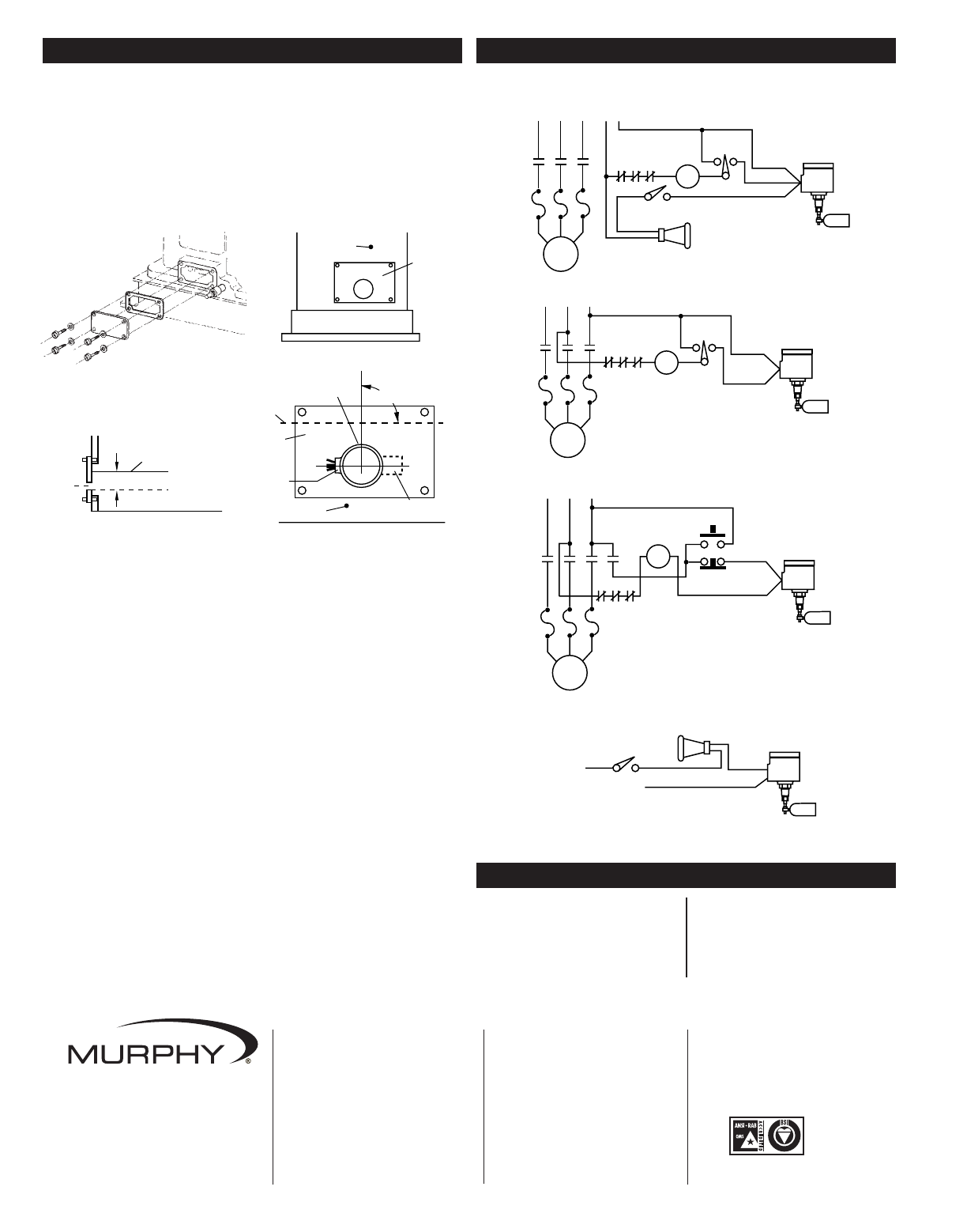
Compressors With Inspection Plate
1. Drain crankcase.
2. Remove crankcase inspection plate (Figure 1).
3. Drill and tap a 1/2 NPT female pipe thread into the inspection plate at
point “A” (Figure 2). CAUTION: Clean area of metal shavings. The
hole is to be a minimum of 2 in. (51 mm) below normal running oil
level (Figure 3).
4. Unscrew and remove float on the L971 switch.
5. Apply pipe dope to the process connection threads.
6. Thread the L971 switch into crankcase hole until “TOP” label is up (Figure
4). Be sure the float moves freely and there are no obstructions.
7. If adjustment of shutdown level is required, loosen hex set screw on float
attachment. Rotate float attachment to desired level. Retighten set screw.
8. Replace float and reinstall inspection plate and gasket in original position.
9. Install drain plug.
10. Wire accordingly.
11. Fill crankcase to proper level.
Compressors Without Inspection Plate
1. If installing into a thick wall crankcase, drill and tap a 1/2 NPT
female pipe thread into the crankcase. CAUTION: Clean area of
metal shavings. The hole is to be a minimum of 2 in. (51 mm) below
normal running oil level (Figure 3).
If installing into a thin wall crankcase, drill a hole in the crankcase
slightly larger than outside diameter of a 1/2 in. coupling. The hole is to
be a minimum of 2 in. (51 mm) below normal running oil level (Figure
3). CAUTION: Clean area of metal shavings. Weld a half collar (1/2
NPT) into the hole.
2. Follow steps 4 thru 11 above.
Normal
Oil Level
Hole
2 in. (51 mm) Minimum
Inspection
Plate
Crankcase
A
Oil Level
Crankcase
Float
90°
“TOP” Label
Inspection
Plate
Conduit
Figure 1
Figure 4
Figure 2
Figure 3
Shutdown Circuit for H.O.A. Operation
H
O
A
HC
Yellow
Black
Line Voltage
Shutdown and Alarm Circuit
Control Voltage
H
O
A
HC
Crankcase
Switch
Crankcase
Switch
Crankcase
Switch
Crankcase
Switch
Alarm Silencer
Alarm
Yellow
Black
Red
Alarm Without Shutdown Circuit
Power Supply
Alarm Silencer
Alarm
Yellow
Red
Shutdown Circuit for Start-Stop Push-button Operation
HC
Yellow
Start
Stop
Black
TYPICAL WIRING
REPLACEMENT PARTS
Description Part Number
Cover 15050443
Cover Gasket 15050369
Snap-switch 00002326
Description Part Number
Float
Polyurethane 15050679
Stainless Steel 15050356
CONTROL SYSTEMS & SERVICES DIVISION
P.O. Box 1819; Rosenberg, Texas 77471; USA
+1 281 633 4500 fax+1 281 633 4588
e-mailsales@fwmurphy.com
MURPHY DE MEXICO, S.A. DE C.V.
Blvd. Antonio Rocha Cordero 300, Fracción del Aguaje
San Luis Potosí, S.L.P.; México 78384
+52 444 8206264 fax +52 444 8206336
Villahermosa Office +52 993 3162117
e-mailventas@murphymex.com.mx
www.murphymex.com.mx
FRANK W. MURPHY, LTD.
Church Rd.; Laverstock, Salisbury SP1 1QZ; U.K.
+44 1722 410055 fax+44 1722 410088
e-mailsales@fwmurphy.co.uk
www.fwmurphy.co.uk
MURPHY SWITCH OF CALIFORNIA
41343 12th Street West
Palmdale, California 93551-1442; USA
+1 661 272 4700 fax+1 661 947 7570
e-mailsales@murphyswitch.com
www.murphyswitch.com
In order to consistently bring you the highest quality, full featured products, we reserve the right to change our specifications and designs at any time.
MACQUARRIE CORPORATION
1620 Hume Highway
Campbellfield, Vic 3061; Australia
+61 3 9358 5555 fax+61 3 9358 5558
e-mailmurphy@macquarrie.com.au
FW Murphy
P.O. Box 470248
Tulsa, Oklahoma 74147 USA
+1 918 317 4100
fax +1 918 317 4266
e-mail sales@fwmurphy.com
www.fwmurphy.com
R
E
G
I
S
T
E
R
E
D
USA–ISO 9001:2000 FM 28221
UK–ISO 9001:2000 FM 29422
Printed in U.S.A.