


FW Murphy – MeCAN MEC300 installation instructions 00-02-0665 28
th
November 2008 p2/3
ELECTRICAL CONNECTION & CONFIGURATION
Electrical connection
MeCAN connection is via 9 colour-coded flying leads
(see diagram on page 1).
RED: Power supply positive DC
BLACK: Power supply negative DC
Connect these wires to a smooth DC power supply in the range
7 to 35 VDC. A 1 Amp anti-surge fuse is recommended in the
positive DC line.
MeCAN operates with negative earth/ground or fully insulated
DC systems. DO NOT use MeCAN with positive earth/ground
systems.
YELLOW: CANbus high
GREEN: CANbus low
Connect these wires to the engine’s CANbus, using the
appropriate twisted-pair cable to J1939 specification. MeCAN
includes a non-removable 120 Ohm CAN terminating resistor.
VIOLET: Speed input signal
YELLOW / GREEN: Speed input return
GREY: Speed input calibration (5kOhm potentiometer)
Connect the violet wire to a magnetic pickup or charge
alternator speed signal output. Connect the yellow/green
wire to the speed signal return wiring (or battery negative,
on ground/ negative-return systems). This input requires a
speed signal of 10 – 60 VAC peak.
Before speed input calibration (see section right), connect
a 5kOhm potentiometer between the grey wire and battery
negative DC. MeCAN allows adjustment for speed signals
between 10 and 180 pulses per engine revolution. The
potentiometer can be removed in normal operation.
BLACK: Sender/switch common (negative DC)
WHITE: Coolant temp sender/switch input
ORANGE: Oil pressure sender/switch input
Part number 79.70.0014 is designed for use with Murphy
ES series resistive senders: see separate product info for
pressure and temperature versus resistance data. For best
measurement accuracy, use insulated return (2-wire) senders.
Connect one terminal of each sender to the appropriate
MeCAN input lead; connect the other sender terminals to
MeCAN’s Sender Common (black) wire. Where 1-wire
(negative DC/ground return) senders are used, connect
the black (sender common) wire to battery negative.
79.70.0020 is configured for use with switch contacts that close
to negative DC on fault. For insulated return (2-wire) switches,
connect one switch terminal to the appropriate MeCAN input;
the second terminal from each switch (on 2-wire switches) or
the body ground (on 1-wire switches) must be connected to
MeCAN’s sender/switch common (black) wire.
Speed input calibration
MeCAN’s speed sensing input must be correctly calibrated
before speed data can be correctly transmitted.
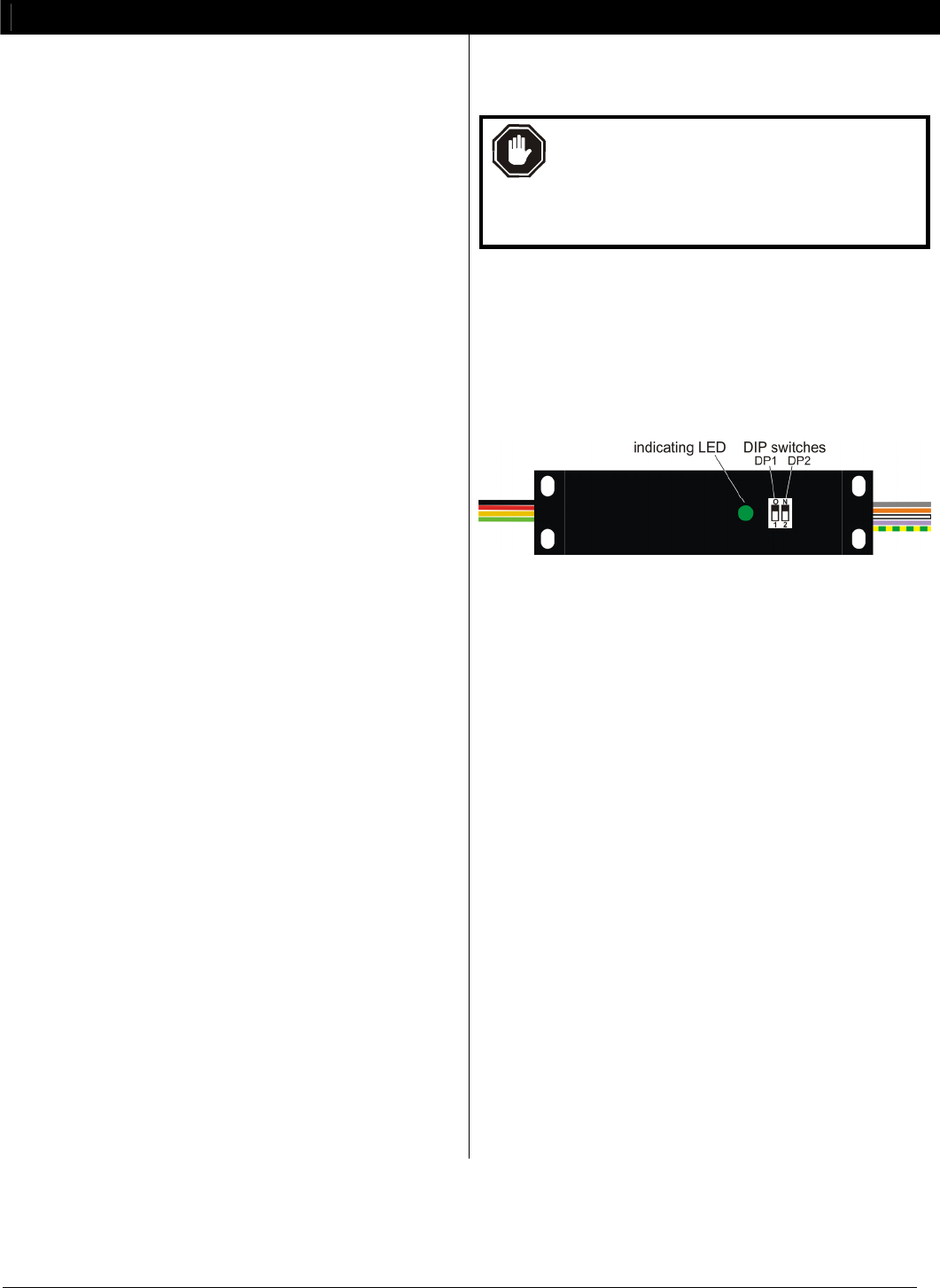
WARNING: speed calibration requires the setting
of 2 DIP switches, which are environmentally
protected by an adhesive film. To maintain sealing
integrity, use a scalpel to carefully lift the film from
the DIP switch, make switch adjustments, then
replace the film firmly to ensure a good seal.
The speed calibration procedure is as follow:-
a) Ensure minimum connection (details shown left) of CANbus,
speed signal and (isolated) DC power supply wiring.
b) Connect a 5 kOhm potentiometer between MeCAN’s
calibration input (grey wire) and battery negative DC.
c) Connect (to the CANbus) and power-up a J1939 compatible
RPM display, e.g. Murphy PowerView® PV101.
d) Set MeCAN switch DP1 to OFF (down) for calibration mode:
e) Set switch DP2 for the speed sensor range, if known:
- ON (up) = 10 to 62 pulses per rev
- OFF (down) = 55 to 180 pulses to rev
f) Run engine to known speed.
g) Power-up MeCAN. The LED flashes rapidly to indicate
calibration mode.
h) Adjust the 5kOhm calibration potentiometer until the J1939
RPM display indicates the known engine speed. If the
indicated speed is too high/low and cannot be adjusted
downward/upward, power down MeCAN, switch DP2 to a
lower/ higher speed range, then repeat the procedure from
g) above.
i) Once the correct speed is indicated (and with MeCAN still
powered), switch DP1 to ON (up) to save the calibration
setting. Normal operation then resumes, indicated by a
continuously lit LED (if CANbus traffic is detected) or a
slow flashing LED if CANbus traffic is not present).
j) Stop the engine and power-down MeCAN. The 5kOhm
calibration resistor is not required for normal operation and
may be removed. Restart the engine, power-up MeCAN and
check for correct operation.
Mounting
MeCAN uses an epoxy-resin filled polycarbonate case for
high impact and environmental resistance. The case is
compact and light enough for inclusion in (or tie-wrapping to)
an engine wiring harness; or it can be surface mounted via 4 x
M4 (0.15 in) holes - see diagram on page 1 for dimensions.