


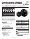
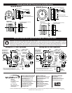
MLA20 and MLA35 Dimensions and Mounting
For Panels up to 3/4 in. (19 mm)
maximum thickness
For Panels up to 3/8 in.
(9.5 mm) maximum thickness
Mounting Clamp
Mounting Hole
2.062 in. (52 mm) Dia.
2.25 in. (57 mm)
1.94 in. (49 mm)
0.48 in. (12 mm)
Push On Plug (Amp)
Connection
1.94 in.
(49 mm)
Mounting Clamp
Mounting Hole
3.375 in. (86 mm) Dia.
3.55 in. (90 mm) 2.0 in. (51 mm)
0.48 in. (12 mm)
3.22 in.
(82 mm)
Push On Plug (Amp)
Connection
For Panels up to 3/4 in. (19 mm)
maximum thickness
For Panels up to 3/8 in.
(9.5 mm) maximum thickness
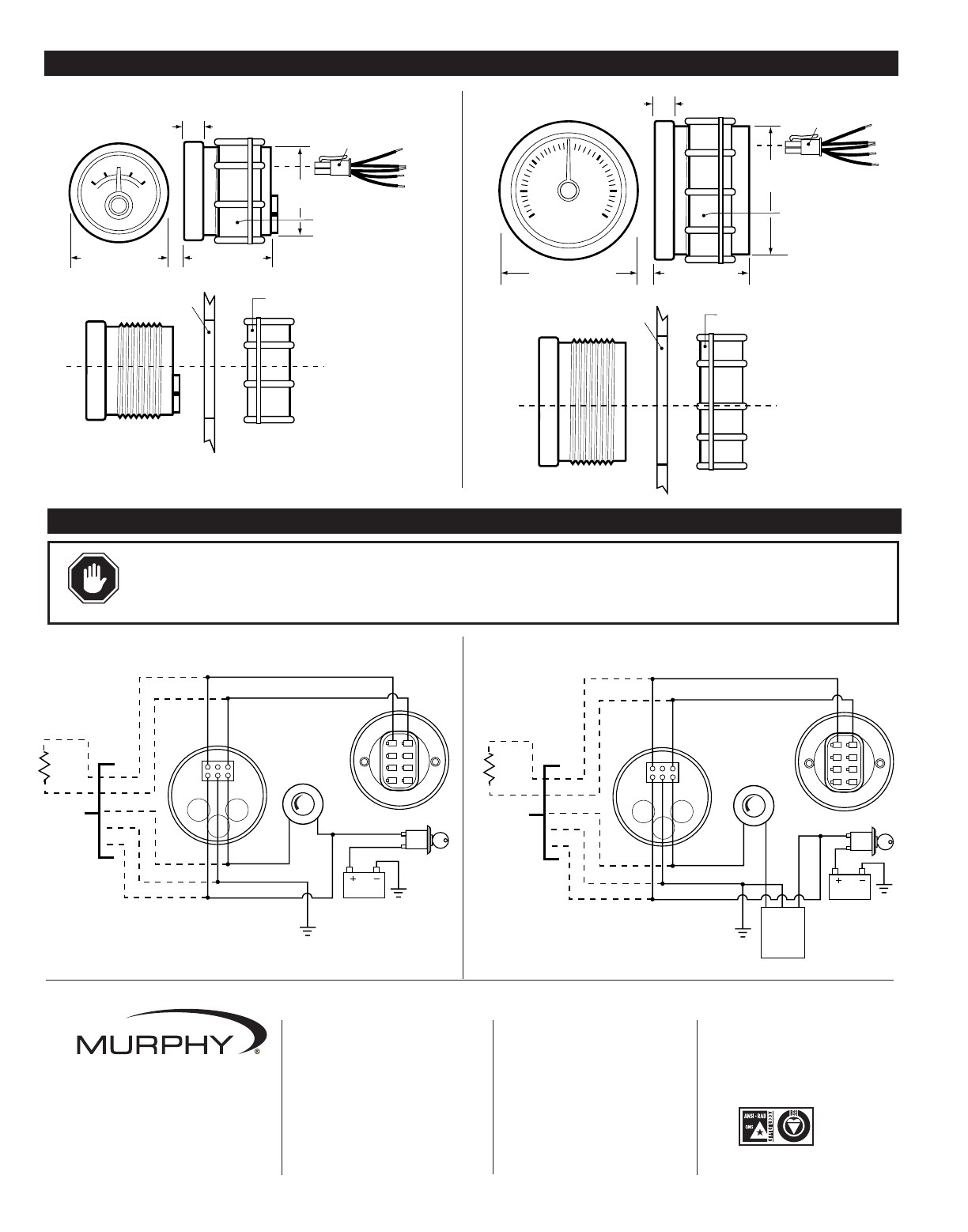
MLA20 Series
MLA35 Series
Orange
Battery
Ignition
Switch
Red
120 Ω
Place Resistor at
End of Line on
Last MLA gage.
(included for factory
purchased panels.)
To Next
MLA Gage
Back
Light
Ground
Battery
Blue
White RS485 (+) Data
RS485 (-) Data
MDDM Gage
Rear View
Illumination
Control*
(optional)
*
Electronic Dimmer switch recommended with 4 A, capacity
or heavy duty rheostat switch, 25 ohm, 5 watt.
For more than 6 MLA gages, contact factory for rheostat sizing.
MLA Gage
Rear View
Pin A
Pin H
Black
Orange
Battery
Ignition Switch
Red
120 Ω
To Next
MLA Gage
Back
Light
Ground
A (V in)
B (Ground)
C (V Out)
Battery
Blue
White RS485 (+) Data
RS485 (-) Data
MDDM Gage
Rear View
Illumination
Control*
(optional)
Back Light
Voltage
Regulator
(MLVC2412)
*
Electronic Dimmer switch recommended with 4 A, capacity
or heavy duty rheostat switch, 25 ohm, 5 watt.
For more than 6 MLA gages, contact factory for rheostat sizing.
MLA Gage
Rear View
Pin A
Pin H
Black
Place Resistor at
End of Line on
Last MLA gage.
(included for factory
purchased panels.)
Wiring for 12 VDC Systems
Wiring for 24 VDC Systems
WARNING:
Disconnect battery negative cable before wiring or service. Devices containing solid state components can be damaged or caused to
malfunction when used in systems which incorporate inductive loads (e.g. relays, solenoids, etc.) that can generate voltage spikes. To reduce the
potential for this type of damage, install a fly back or clamping diode across all inductive loads. Use Murphy diode package 65-00-0343 or equivalent.
A typical diode is 1N4005 and is readily available from commercial sources. Failures of this type are not covered by our Limited Warranty.
MLA20 and MLA35 Typical Wirings For 12 and 24 VDC
Installation MLA-00012N page 2 of 2
CONTROL SYSTEMS & SERVICES DIVISION
P.O. Box 1819; Rosenberg, Texas 77471; USA
+1 281 633 4500 fax+1 281 633 4588
e-mailsales@fwmurphy.com
MURPHY DE MEXICO, S.A. DE C.V.
Blvd. Antonio Rocha Cordero 300, Fracción del Aguaje
San Luis Potosí, S.L.P.; México 78384
+52 444 8206264 fax +52 444 8206336
Villahermosa Office +52 993 3162117
e-mailventas@murphymex.com.mx
www.murphymex.com.mx
FRANK W. MURPHY, LTD.
Church Rd.; Laverstock, Salisbury SP1 1QZ; U.K.
+44 1722 410055 fax+44 1722 410088
e-mailsales@fwmurphy.co.uk
www.fwmurphy.co.uk
MURPHY SWITCH OF CALIFORNIA
41343 12th Street West
Palmdale, California 93551-1442; USA
+1 661 272 4700 fax+1 661 947 7570
e-mailsales@murphyswitch.com
www.murphyswitch.com
In order to consistently bring you the highest quality, full featured products, we reserve the right to change our specifications and designs at any time.
MACQUARRIE CORPORATION
1620 Hume Highway
Campbellfield, Vic 3061; Australia
+61 3 9358 5555 fax+61 3 9358 5558
e-mailmurphy@macquarrie.com.au
FW Murphy
P.O. Box 470248
Tulsa, Oklahoma 74147 USA
+1 918 317 4100
fax +1 918 317 4266
e-mail sales@fwmurphy.com
www.fwmurphy.com
R
E
G
I
S
T
E
R
E
D
USA–ISO 9001:2000 FM 28221
UK–ISO 9001:2000 FM 29422
Printed in U.S.A.