


MTH-96116N page 2 of 2
WIRING AND OPERATION
Wiring the MTH6
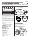
Refer to Typical Wiring Diagram, below.
Operation Sequence and Adjustments
When power is applied, the MTH6 performs an LCD test displaying
counting down to zero within 3 seconds. The MTH6 will perform
a normal scan, and will begin to monitor engine RPM. When the unit is in
Normal Scan, it displays RPM. The display is updated internally every second.
Viewing the Elapsed Time Hours
( )
1.
To view the elapsed hours, press
ENTER
(
■■
) while in Normal Scan.
2.
will be displayed followed by elapsed hours.
3.
To clear/reset to zero, apply a momentary ground to terminal #5. The hourme-
ter cannot be reset when a speed signal is present (normal operation).
NOTE: When speed input is present the first digit and decimal point will
flash. Decimal point will NOT appear after 10,000 hours have elapsed.
Pulses Per Revolution
( )
Calibration
1.
To view the current pulses per engine revolution, press
ENTER
(
■■
) while
in Normal Scan. will be displayed followed by the running hours.
2.
Press
ENTER
(
■■
). will be displayed followed by the present number
of pulses per revolution. The factory setting is 60. Unit will display input fre-
quency with this setting.
3.
To calculate the pulses per engine revolution ( ) follow the instructions:
Magnetic Pickup: Determine the number of teeth on the engine’s flywheel.
The number of teeth is equal to the number of pulses per engine revolution.
Battery Charging Alternator: Multiply the ratio of alternator to engine
pulley diameter, times, the number of poles of the alternator divided by 2
to determine the correct pulses per engine revolution.
When the number of pulses per revolution is unknown, follow this procedure:
1. Set the pulses per revolution on the MTH6 to “60”.
2. Run the engine at a constant speed and measure the actual RPM using a hand-
held tachometer or any means which measures actual RPM.
3. Read the RPM displayed on the MTH6 (this is the frequency in hertz caused by
the engine speed).
4. Multiply the RPM reading on the MTH by 60, then divide by the actual RPM
read by the handheld device. Set this resulting number as the pulses per revolution
on the MTH6.
NOTE: If pulses per revolution are not a whole number, for example: 21.5, a
setting of 21 will read slightly high and a setting of 22 will read slightly low.
4.
To change the setting first remove the input signal. Press
UP
(
▲▲
) to
increase the value. Press
DOWN
(
▼▼
) to decrease the value.
5.
Once the number of pulses per revolution is set, press
ENTER
(
■■
) to save.
is displayed indicating that the new number is saved.
6.
Connect the input signal back in place (refer to typical wiring diagram at left).
Overspeed Set Point (HISP) Calibration
1.
To view the current Overspeed set point, press
ENTER
(
■■
) while the
MTH6 is in Normal Scan.
2.
will be displayed followed by the amount of elapsed hours.
3.
Press
ENTER
(
■■
) with elapsed time visible. will be displayed fol-
lowed by the number of pulses per revolution.
4.
Press
ENTER
(
■■
). will be displayed followed by the overspeed set
point previously entered. Factory setting is 1500.
5.
Press
UP
(
▲▲
), to increase the overspeed setting. Press
DOWN
(
▼▼
) to
decrease the setting.
6.
Press
ENTER
(
■■
), will be displayed indicating that the new value
is now saved.
Shield
Grd.
Magnetic Pickup
Alternator
See Note 3
Tachometer
terminal
See Note 4
See
Note 2
See
Note 1
NOTE 2: When using the MTH6 with inductive
loads, we recommend installing a
suppression diode across all coils.
NOTE 3: Terminals 4 and 8 may be grounded
on negative ground power supply.
NOTE 4: Alternator must be equipped with a
tach terminal (auxiliary AC terminal).
NOTE 1: Apply momentary ground to reset
hours to zero.
Overspeed Load 2 A, 50 Vdc
(example: 518PH TATTLETALE
®
magnetic switches; SAH MINI-SIREN
®
;
TL7 Flashing Alarms)
Display
Light
Switch
+
--
Supply
8-40 Vdc
1
2
3
4
5
6
7
8
9
CAUTION: Connecting full battery
potential to terminal 9 can cause damage
to the SWICHGAGE
®
. Shutdown circuit
is rated for 300 mA continuous.
Circuit grounds out at set point.
WARNING:
Disconnect All Power before performing
wiring operation. Keep power leads away from input leads.
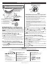
Display
Up
Overspeed
Set Point
LED (light)
Enter or
Aknowledge
Down
®
FRANK W.
MTH6
MFR.
ENTER
SETPOINT
MTH6 Back View
MTH6 Module Detail
Warranty
A limited warranty on materials and workmanship is given with this FW Murphy product.
A copy of the warranty may be viewed or printed by going to www.fwmurphy.com/support/warranty.htm
INDUSTRIAL PANEL DIVISION
P.O. Box 470248
Tulsa, Oklahoma 74147 USA
+1 918 317 4100 fax +1 918 317 4266
e-mail sales@fwmurphy.com
MURPHY DE MEXICO, S.A. DE C.V.
Blvd. Antonio Rocha Cordero 300, Fracción del Aguaje
San Luis Potosí, S.L.P.; México 78384
+52 444 8206264 fax +52 444 8206336
Villahermosa Office +52 993 3162117
e-mail ventas@murphymex.com.mx
www.murphymex.com.mx
FRANK W. MURPHY, LTD.
Church Rd.; Laverstock, Salisbury SP1 1QZ; U.K.
+44 1722 410055 fax +44 1722 410088
e-mail sales@fwmurphy.co.uk
www.fwmurphy.co.uk
In order to consistently bring you the highest quality, full featured products, we reserve the right to change our specifications and designs at any time.
FW Murphy
P.O. Box 470248
Tulsa, Oklahoma 74147 USA
+1 918 317 4100 fax +1 918 317 4266
e-mail sales@fwmurphy.com
www.fwmurphy.com
Printed in U.S.A.