


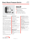
2-1/4 in.
(57 mm)
NO C NC
2-9/16 in.
(65 mm)
1/2 in. (13 mm)
Square wrench flats
1/8-27 NPT
2-1/32 in. Dia.
(52 mm)
Slot head terminal
screws (4-40, UNC-2A)
Dimensions
Installation Instructions
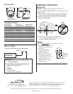
Mounting
CAUTION:
Use wrench on shank to tighten or loosen pressure
connection. DO NOT TWIST CASE, which will damage the unit and
void the warranty.
1. Before installing the PSB switch, apply sealant, such as Teflon tape,
to the threads (be sure sealant does not block the inlet orifice).
2. The PSB can be mounted in horizontal or vertical angles (do not
mount switch facing down).
3. Locate the unit in place and secure it by tightening
the 1/8-27 NPT fitting into the desired location (do not
overtighten). DO NOT TWIST CASE.
Trip Point Chart
Ranges available Factory setting
*
Maximum pressure
psi (kPa/MPa) [bar] psi (kPa) [bar] Falling psi (kPa) [bar]
0-15 (0-103) [0-1.03] 3 (21) [.21] 30 (207) [2.07]
0-30 (0-207) [0-2.07] 7 (48) [.48] 60 (414) [4.14]
0-50 (0-345) [0-3.45] 10 (69) [.69] 100 (0-689) [0-6.89]
0-75 (0-517) [0-5.17] 15 (103) [1.03] 150 (0-1.03) [0-10.34]
0-100 (0-689) [0-6.89] 20 (138) [1.38] 200 (0-1.38) [0-13.79]
0-150 (0-1.03) [0-10.34] 30 (207) [2.07] 300 (0-2.07) [0-20.70]
0-200 (0-1.38) [0-13.79] 50 (345) [3.45] 400 (0-2.76) [0-27.60]
0-300 (0-2.07) [0-20.70] 75 (517) [5.17] 500 (3.45) [34.50]
0-400 (0-2.76) [0-27.60] 150 (1.03) [10.34] 500 (3.45) [34.50]
*
These points will be used if switch trip point is not specified.
WRONG
UP
M
o
u
n
t
i
n
g
A
n
g
l
e
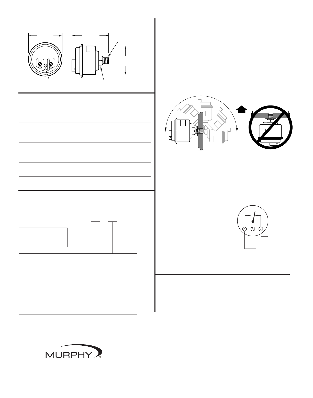
Wiring
CAUTION:
DISCONNECT Electrical power before wiring.
1. Switch contacts (below) are shown
with no pressure applied to the
PSB switch.
2. A spade (forked) terminal
is recommended for all
PSB switch connections.
3. Complete the wiring operation
making sure the voltage and
current requirements are within
the PSB switch electrical
rating (see the typical wiring
diagram at right).
Normally
Closed (N.C.)
Normally
Open (N.O.)
Common (C)
PSB-9104B page 2 of 2
PSB – –
To order the PSB model use the diagram below.
Pressure Range
Specify maximum value
from chart above.
Switch Trip Point
†
F = Factory set to trip on falling. Specify “F” and the set point value.
Example: PSB-100-F20.
R = Factory set to trip on rising, Specify “R” and the set point value.
For units of measure other than psi, specify the set point value
followed by unit of measure as follows:
B = Bar
K = kPa/MPa
M = kg/cm2
Example: PSB-7B-2B
†
Switch set point value will be stated on label.
How to Order
In order to consistently bring you the highest quality, full featured products, we reserve the right to change our specifications and designs at any time.
Printed in U.S.A. 0591124M
In order to consistently bring you the highest quality, full featured products, we reserve the right to change our
specifications and designs at any time. MURPHY, the Murphy logo are registered and/or common law
trademarks of Murphy Industries, Inc. This document, including textual matter and illustrations, is copyright
protected by Murphy Industries, Inc., with all rights reserved. (c) 2006 Murphy Industries, Inc.
www.fwmurphy.com
918.317.4100 Email: sales@fwmurphy.com