


Power Consumption: 120 VAC (8 watts), 12 or 24 VDC (2.5 or 7.2 watts).
Sensor Inputs: 32 N.O. and/or N.C., such as Murphy SWICHGAGE
®
instru-
ments. Inputs are factory-programmed as a Class A, B, C or P for shutdown,
alarm, or control function (specify).
Opto-Isolated Input: 12-120 VDC or 24-120 VAC, the opto-isolated input is
typically used as a run input, magnetic pickup and ignition.
Outputs: 4-SPDT relays, 4 A,
1
/20 HP, 125/250 VAC/3A, 30 VDC.
NOTE: An approved isolation barrier must be used between the sensor
switch and input terminals if the sensor output comes from any energy stor-
ing device such as a relay or transistor. (See LCDT-ISB
Barrier, at right).
Timers: 12 adjustable timers for:
•
Two Start-up lockouts
•
Test
•
Prelube
•
Postlube
•
Load delay
•
Idle
•
Crank
•
Rest
•
Run delay
•
Process delay
•
Ignition ground
Time Delay: Delay before ignition ground or electric motor stop, for
up to 59 seconds.
Terminal Block: Rail mount DIN type; 32 positions (screw type).
Backup Battery: Rechargeable during normal operation.
Provides up to 5 hours backup time.
Tachometer Sensing: From either CD Ignition or Magnetic Pickup.
Operating Temperatures: 32 to 122°F (0 to 50°C).
Storage Temperatures: -4 to 158°F (-20 to 70°C).
Case: ABS plastic,
1
/4 DIN (90 x 90 mm).
Interface Output: RS232 communication port.
Alphanumeric Display: 2 lines, each line with 16 characters (32 total).
Laboratory Approvals: CSA and NRTL/C for Cl. I, Div. 1, Grps. C & D.
Power Supply Enclosure: Explosion-proof, Class I, Division 1. Intrinsically
safe barrier built into power supply, 120 VAC and 12 or 24 VDC power
supply barrier with dry contact relay functions such as:
•
Fuel valve
•
Alarm
•
Shutdown
•
Ignition
•
Control (Pre/Postlube)
•
Compressor Loading
•
Engine Cranking
LCDT-ISB Intrisically Safe Barrier
:
External barrier explosion-proof design for hazardous locations, according
to NEC requirements for Class 1, Division 1 Group D areas. The LCDT-ISB
accepts Normally Open sensor inputs (2 inputs per barrier). For Normally
Closed sensors, an intrinsically safe (approved) barrier is required.
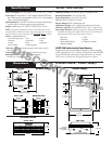
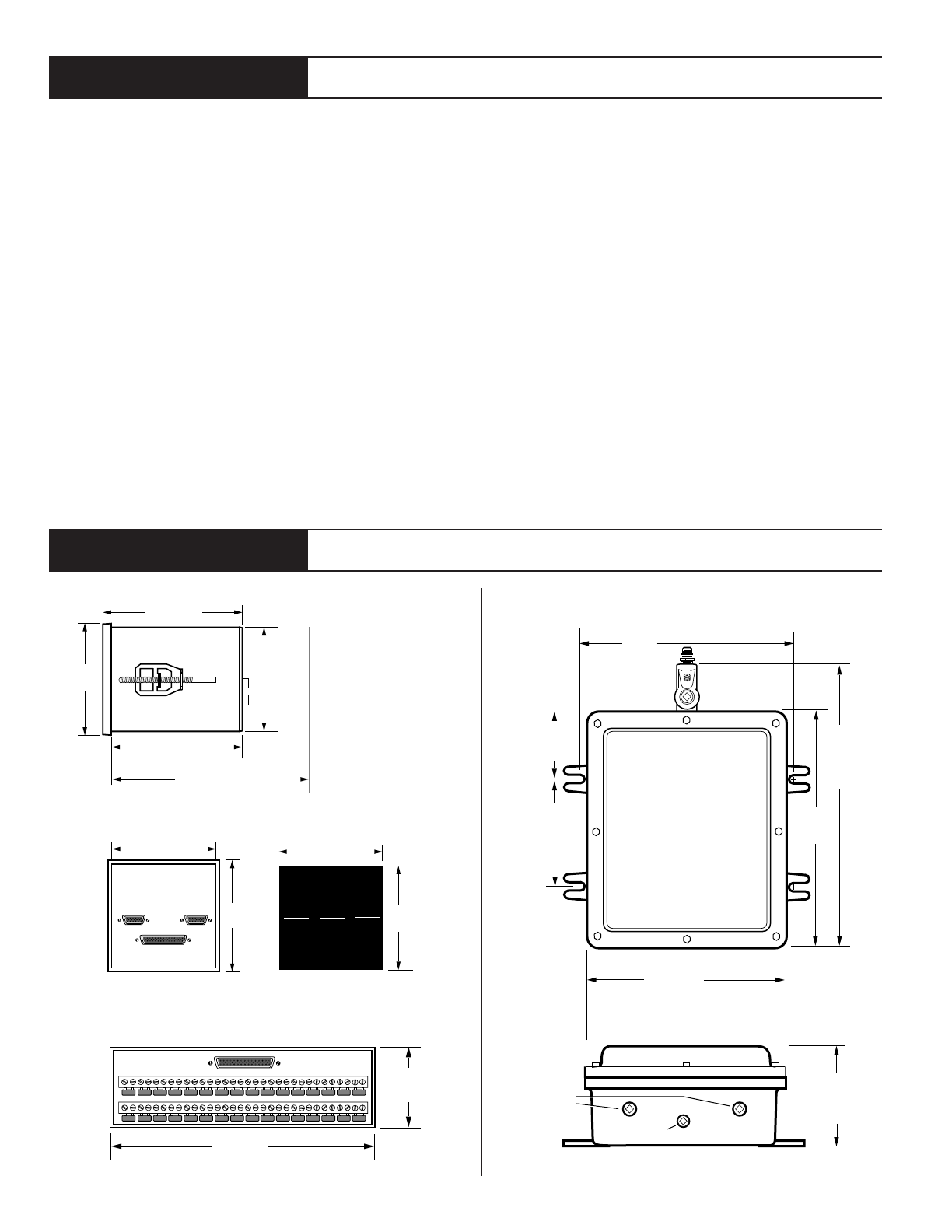
6 in.
(152 mm)
10-1/2 in.
(267 mm)
8-3/4 in.
(222 mm)
15 in.
(381 mm)
clearance
for conduit
4-1/2 in.
(114 mm)
3 in.
(76 mm)
TOP VIEW
SIDE VIEW
9 in.
(229 mm)
3/4 NPT
conduit fittings
(2) places
1/2 NPT conduit fitting
3-1/2 in.
(89 mm)
3-3/4 in.
(95 mm)
3-1/2 in.
(89 mm)
4-3/8 in.
(111 mm)
4-5/8 in.
(117 mm)
3-3/4 in.
(95 mm)
BACK VIEW
SIDE VIEW
3-9/16 in.
(90 mm)
3-9/16 in.
(90 mm)
MOUNTING HOLE
6-3/4 in.
(171 mm)
clearance for plug
Mounting
Clamp
7 in.
(178 mm)
3-1/32 in.
(77 mm)
FRONT VIEW
Specifications
Dimensions
Module, Terminal Block, Power Supply
Series 1500 System
Terminal Block
Power Supply
Module (Head)
DISCONTINUED