


SS-97028N page 2 of 4
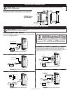
MOUNTING DIMENSIONS
The SS300 Series models can be mounted to a flat surface within
the panel using two #8 screws. Mounting screws are not supplied.
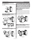
TYPICAL WIRING INSTALLATION
CAUTION:
BEFORE PERFORMING THE WIRING OPERATION TURN THE POWER SOURCE
OFF AND STOP YOUR ENGINE.
CAUTION:
THE SS300 SERIES MODELS ARE INTENDED FOR INSTALLATION WITHIN A WEATHER-
PROOF ENCLOSURE.
Battery
Magnetic Pickup
+--
Ignition
Switch
SS300
4 INPUT
3
2
1
5 – BATT.
6 + BATT.
7
8
SPEED
GND. FOR
T/D
POS. TO
LATCH
Battery
Ignition
Switch
Fuel
Solenoid
Speed
Signal
+--
SS300
4 INPUT
3
2
1
5 – BATT.
6 + BATT.
7
8
SPEED
GND. FOR
T/D
POS. TO
LATCH
Battery
Ignition
Switch
Energize to stop
Solenoid
Speed
Signal
+--
SS300
4 INPUT
3
2
1
5 – BATT.
6 + BATT.
7
8
SPEED
GND. FOR
T/D
POS. TO
LATCH
Battery
To Alternator
Tach. Terminal
Ignition
Switch
+--
SS300
4 INPUT
3
2
1
5 – BATT.
6 + BATT.
7
8
SPEED
GND. FOR
T/D
POS. TO
LATCH
Battery
Ignition
Switch
+
--
Coil
+--
SS300
4 INPUT
3
2
1
5 – BATT.
6 + BATT.
7
8
SPEED
GND. FOR
T/D
POS. TO
LATCH
Figure 1:
Magnetic Pickup Input
Figure 2:
Alternator Tach., Input
Figure 3:
Distributor Ignition Input
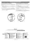
Figure 5:
Energize to Stop Solenoid
CAUTION:
If replacing an SS100 Series
model with an SS300 Series model, note the
significant wiring differences on the SS300
terminals: 5, 6, 7, and 8. Wire your SS300 accordingly.
Figure 4:
Energize to Run Solenoid
Frequency/RPM Input Source
Connect the SS300 Series speed switch to the appropriate frequency/RPM
input source. See Figures 1 thru 3.
Latching Overspeed with Fuel Solenoid
A latching overspeed switch with fuel solenoid application is shown in
Figures 4 and 5. Ignition switch must be turned off to unlatch.
2-1/2 in.
(64 mm)
2 in.
(51 mm)
3/16 in. (5 mm)
dia. two places
2-1/16 in.
(52 mm)
1-1/32 in.
(26 mm)
3 in.
(76 mm)
SS300 Series
(all models)