


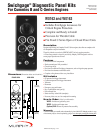
CMNS-97077B page 2 of 2
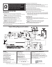
INSTALLATION INSTRUCTIONS
Open Power Unit
1. Remove battery ground and secure to prevent unintentional contact.
2. Attach oil line to pressure Swichgage. Use sealant tape or pipe dope.
CAUTION: Do not allow sealant to plug pressure Swichgage orifice.
3. Feed wire harness through bottom 2 in. (51 mm) dia. hole in bracket.
4. Feed oil line through upper 2 in (51 mm) dia. hole in bracket.
5. Install panel onto mounting bracket and secure.
6. Install oil line into engine oil galley. Use sealant tape or pipe dope.
7. Install temperature sensing bulb into water jacket.
CAUTION: Be sure capillary tube is routed away from exhaust manifold.
8. Connect wire 7A to hot terminal of fuel solenoid.
9. Connect wire 8A to engine block (ground).
10. Mount starter solenoid (auxiliary magnetic switch) to bracket 30050670 and mount
assembly to engine below starter.
11. Connect wire 11B to starter terminal “S”.
12. Connect wires 6A, 9B, and 10B to starter terminal “Batt”.
13. Connect wire 10A to either of the large terminals on starter solenoid (auxiliary mag-
netic switch). Connect wire 11A to other large starter solenoid terminal.
14. Connect wire 5A to either of the small terminals on the starter solenoid. Connect
wire 13A to the other small terminal.
15. Connect plug (wires 1A, 4A, and 12A) to alternator.
16. Connect wire 9A and 12B to battery terminal on alternator.
17. Be sure all connections are tight and reconnect battery ground cable.
18. Service engine according to manufacturer’s instructions.
19. To start engine, depress and hold red reset button on panel face (518PH
magnetic switch) while cranking. Observe that oil pressure has been established
and release reset button. If reset button “pops out” engine will stop. Refer to the
518PH installation operation instructions.
Closed Power Unit
1.Remove battery ground and secure to prevent unintentional contact.
2.Enlarge panel cutout on engine enclosure to fit hole pattern on panel face and
expose full panel face.
3.Attach oil line to pressure Swichgage. Use sealant tape or pipe dope.
CAUTION: Do not allow sealant to plug pressure Swichgage orifice.
4.Attach Swichgage panel assembly to rear side of cutout.
5.Follow steps 7 through 19 for open power units.
BEFORE BEGINNING INSTALLATION OF THIS MURPHY PRODUCT
✔✔
Disconnect all electrical power to the machine.
✔✔
Make sure the machine cannot operate during installation.
✔✔
Follow all safety warnings of the machine manufacturer.
✔✔
Read and follow all installation instructions.
WARNING
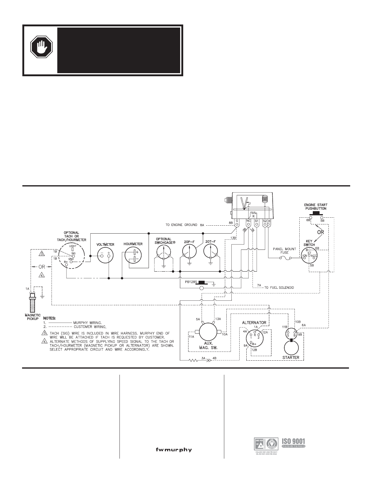
Typical Wiring Diagram (all models)
In order to consistently bring you the highest quality, full featured products, we reserve the right to change our specifications and designs at any time.
FRANK W. MURPHY, LTD
Church Rd Laverstock
Salisbury SP1 1QZ UK
Phone: +44 172 241 0055 Fax: +44 172 241 0088
E-mail: sales@fwmurphy.co.uk
Web site: www.fwmurphy.co.uk
COMPUTRONIC CONTROLS, LTD
41 - 43 Railway Terrace
Nechells, Birmingham B7 5NG UK
Phone: +44 121 327 8500 Fax: +44 121 327 8501
E-mail: sales@computroniccontrols.com
Web site: www.computroniccontrols.com
FW MURPHY INSTRUMENTS (HANGZHOU) CO. LTD
77 23rd Street
Hangzhou Economic & Technological Development Area
Hangzhou, Zhejiang 310018 China
Phone: +86 571 8788 6060 Fax: +86 571 8684 8878
FW MURPHY INTERNATIONAL TRADING (SHANGHAI) CO., LTD.
Suite 1784, Tower B, City Center of Shanghai; 100 Zunyi Road
Shanghai, 200051 China
Phone: +86 21 6237 2082 Fax: +86 21 6237 2083
Web site: mhong@fwmurphy.com
FW MURPHY
P.O. Box 470248
Tulsa, Oklahoma 74147 USA
+1 918 317 4100 Fax: +1 918 317 4266
E-mail: sales@fwmurphy.com
INDUSTRIAL PANEL DIVISION
Fax: +1 918 317 4124
E-mail: ipdsales@fwmurphy.com
MURPHY POWER IGNITION
Web site: www.murphy-pi.com
CONTROL SYSTEMS & SERVICES DIVISION
P.O. Box 1819
Rosenberg, Texas 77471 USA
Phone: +1 281 633 4500 Fax: +1 281 633 4588
E-mail: sales@fwmurphy.com
Printed in U.S.A.
www. .com