47
Chapter 6 Reference
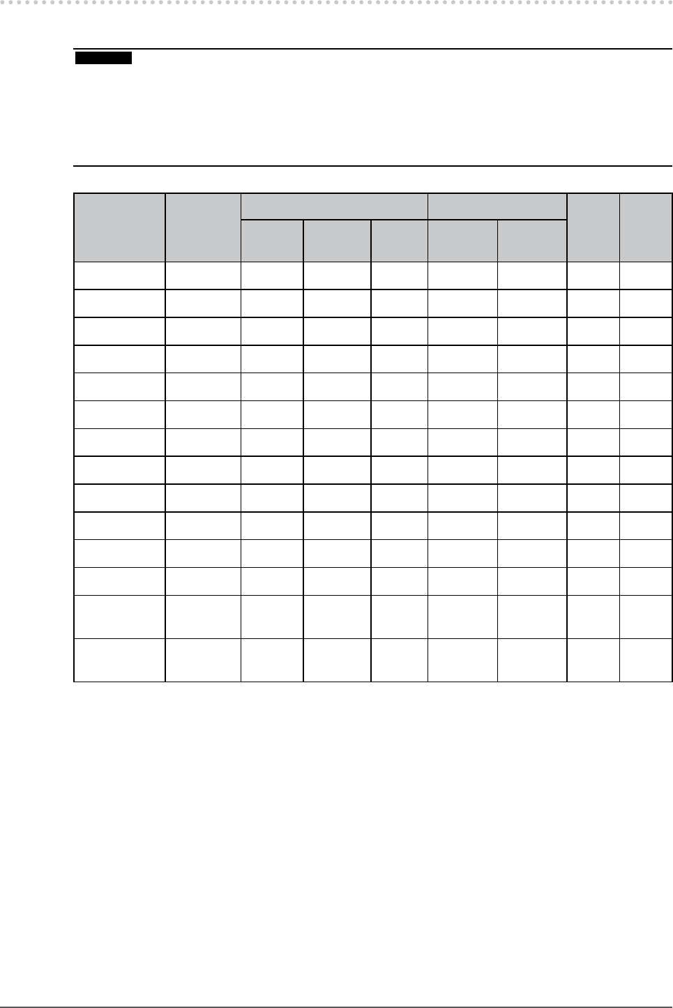
6-7. Preset Timing
The following table shows factory preset video timing (for analog signal only).
Attention
Display position may be deviated depending on the PC connected, which may require screen adjustment using
Adjustment menu.
If a signal other than those listed in the table is input, adjust the screen using the Adjustment menu. However,
screen display may still be incorrect even after the adjustment.
When interlace signals are used, the screen cannot be displayed correctly even after screen adjustment using the
Adjustment menu.
•
•
•
Resolution
Applicable
signal
Frequency Polarity
CG223W CG243W
Dot clock
: MHz
Horizontal
: kHz
Vertical
: Hz
Horizontal Vertical
640 × 480 VGA 25.18 31.47 59.94
Negative Negative
√ √
720 × 400 VGA TEXT 28.32 31.47 70.09
Negative Positive
√ √
800 × 600 VESA 40.00 37.88 60.32
Positive Positive
√ √
1024 × 768 VESA 65.00 48.36 60.00
Negative Negative
√ √
1024 × 768 VESA 75.00 56.48 70.07
Negative Negative
√
―
1024 × 768 VESA 78.75 60.02 75.03
Positive Positive
√
―
1024 × 768 VESA 94.50 68.68 85.00
Positive Positive
√
―
1152 × 864 VESA 108.00 67.50 75.00
Positive Positive
√
―
1280 × 960 VESA 108.00 60.00 60.00
Positive Positive
√ √
1280 × 1024 VESA 108.00 63.98 60.02
Positive Positive
√ √
1600 × 1200 VESA 161.99 75.00 60.00
Positive Positive
―
√
1680 × 1050 VESA CVT 146.25 65.29 59.95
Negative Positive
√ √
1680 × 1050
VESA CVT
RB
119.00 64.67 59.88
Positive Negative
√
―
1920× 1200
VESA CVT
RB
154.00 74.04 59.95
Positive Negative
―
√


