


Chapter 4 Theory of Operation
© National Instruments Corporation 4-15 SCXI-1141/1142/1143 User Manual
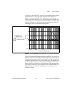
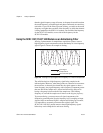
For best results, the cutoff frequency of a particular filter should remain
within this range. If the cutoff frequency goes above this range, the
prefilters and postfilters interfere with signals in the passband, causing
additional attenuation near the cutoff frequency. If the cutoff frequency
goes below this range, the level of protection from aliasing within the filter
and from imaging in the output decreases.
DC-Correction Circuitry and Overload Recovery
The SCXI-1141/1142/1143 module incorporates circuitry that corrects for
the DC gain and offset errors of the filters, leaving only the errors of the
amplifiers. However, this correction circuitry takes approximately 15 s to
completely respond to changes in these errors due to overload conditions
(caused by driving the output signal outside of the ±5 V range) and upon
power-up (no data should be taken during the first 15 s). Overload
conditions result whenever the input signal exceeds ±5 V/gain. You must
use a gain setting that prevents the maximum input signal from exceeding
this limit, or the DC-correction circuitry will take 15 s to recover from
overloads.
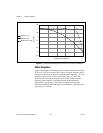
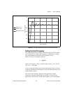
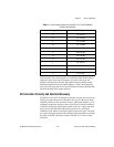
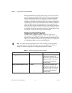
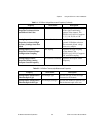
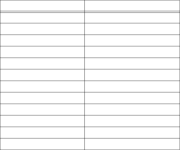
Table 4-1. Cutoff Frequency Ranges for the SCXI-1141/1142/1143 Module
Prefilters and Postfilters
Range Cutoff Frequencies
A 10–25 kHz
B 4.3–10 kHz
C 1.9–4.4 kHz
D 1.5–3.4 kHz
E 700 Hz–1.8 kHz
F 300–700 Hz
G 130–300 Hz
H 100–225 Hz
I 49–110 Hz
J 21–49 Hz
K 15–21 Hz
L 10–15 Hz