


© National Instruments Corporation 13 NI USB-622x/625x/628x OEM User Guide
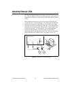
Attaching External LEDs
USB-622x/625x/628x OEM devices have two LEDs that reflect the device
state. The green READY LED indicates when the device is powered on and
configured as a USB device. The yellow ACTIVE LED indicates USB bus
activity.
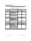
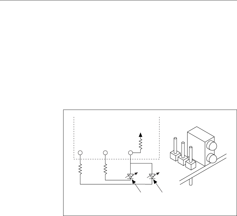
Three connectors on the device allow you to connect an external LED
circuit to the device, as shown in Figure 10. To connect an external READY
LED, use E1 as the positive connection (+3.3 V) and E2 as the negative
connection. To connect an external ACTIVE LED, use E1 as the positive
connection and E3 as the negative connection. E1 is current limited with
a 100 Ω resistor to the 3.3 V internal supply. This configuration limits
the current to approximately 16 mA into a single external LED or
approximately 8 mA each when both LEDs are lit. You also can limit this
current further by using external resistors, also shown in Figure 10.
Figure 10. Schematic for External LED Circuits
E1
External
READY
LED
External
ACTIVE
LED
E2
E3
100 Ω
3.3 V
OEM (On-Board)
E1E2E3