


© National Instruments Corporation 13 cFP-20xx Quick Start Guide
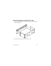
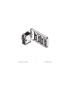
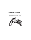
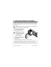
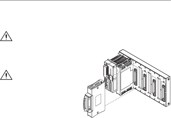
4. Install Connector Blocks on the Backplane
In order to connect I/O modules to input signals or to external loads, you need
to install a cFP-CB-x connector block or other connectivity accessory for each
I/O module on the backplane. Use the connector socket to the right of each I/O
module socket.
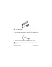
Caution Do not insert or remove connector blocks or other connectivity
accessories while power is applied to them.
1. Wire field devices as described in
the I/O module and connector
block operating instructions.
Caution Hazardous voltage
wiring should be performed
by qualified personnel and
in accordance with local
electrical standards.
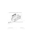
2. Align the captive screws on the
connector block with the holes
on the backplane.
3. Press firmly to seat the connector block on the backplane.
4. Using a number 2 Phillips screwdriver with a shank of at least 64 mm (2.5 in.)
length, tighten the captive screws to 1.1 N · m (10 lb · in.) of torque.
5. Repeat this procedure to install additional connector blocks on the backplane.