


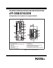
© National Instruments Corporation 7 cFP-2200/2210/2220
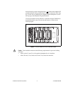
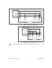
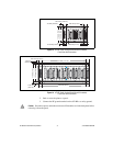
3. Press down firmly on the backplane to compress the spring until the
clip locks in place on the DIN rail.
4. Connect the PE ground terminal on the backplane to safety ground.
Caution Disconnect power and make sure that no I/O modules are in the backplane before
removing it from the DIN rail.
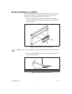
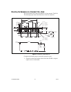
Mounting the Backplane on a Panel
The horizontal panel-mount kit has mounting holes on the sides of the
backplane and is NI part number 778616-01. The vertical panel-mount kit
has mounting holes on the top and bottom of the backplane and is NI part
number 778688-01. Complete the following steps to mount the system on
a flat surface.
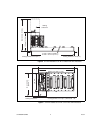
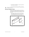
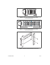
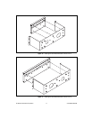
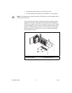
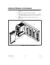
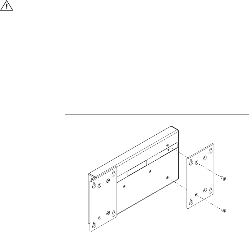
1. Fasten the panel-mount plates to the back of the cFP-BP-x using a
number 2 Phillips screwdriver and the 8-32 × 5/16 in. countersink
screws shipped with the kit. You must use these screws because they
are the correct depth and thread for the plates and backplane.
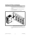
Figure 9. Installing the Horizontal Panel-Mount Kit on the cFP-BP-4
NATION
AL
INSTRUMENTS